
MKS AWD V6-3.7L (2009)
-------------------------------------------------
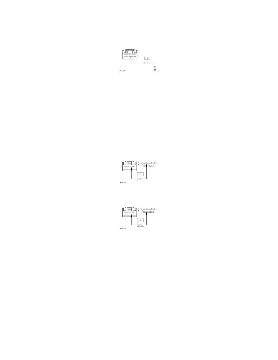
Q2 CHECK THE PAM GROUND CIRCUIT FOR AN OPEN
-
Ignition OFF.
-
Measure the resistance between the PAM C4014-4 or C4226a-4, circuit GD149 (BK/GY), harness side and ground.
-
Is the resistance less than 5 ohms?
Yes
GO to Q3.
No
REPAIR the circuit. TEST the system for normal operation.
-------------------------------------------------
Q3 CHECK THE MS-CAN CIRCUITS BETWEEN THE PAM AND THE DLC FOR AN OPEN
-
Measure the resistance between the PAM C4014-3 or C4226a-3, circuit VDB06 (GY/OG), harness side and the DLC C251-3, circuit VDB06
(GY/OG), harness side.
-
Measure the resistance between the PAM C4014-11 or C4226a-11, circuit VDB07 (VT/OG), harness side and the DLC C251-11, circuit VDB07
(VT/OG), harness side.
-
Are the resistances less than 5 ohms?
Yes
GO to Q4.
No
REPAIR the circuit in question. CLEAR the DTCs. REPEAT the network test with the scan tool.
-------------------------------------------------
Q4 CHECK FOR CORRECT PAM OPERATION
-
Disconnect the PAM connector.
-
Check for:
-
corrosion
-
damaged pins
-
pushed-out pins
-
Connect the PAM connector and make sure it seats correctly.
-
Operate the system and verify the concern is still present.
-
Is the concern still present?