
MKS AWD V6-3.7L (2009)
-
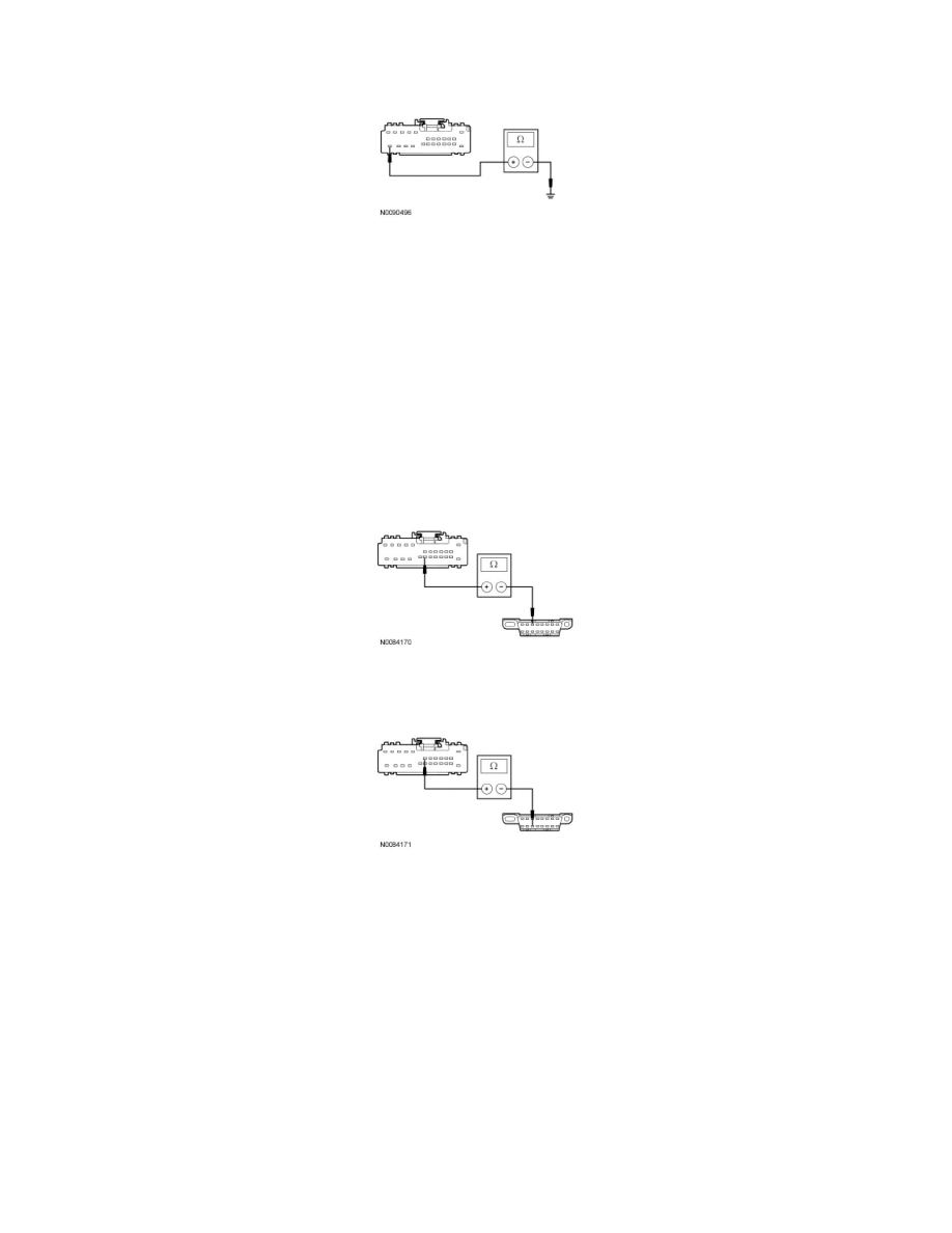
Measure the resistance between the DDM C501a-24, circuit GD133 (BK), harness side and ground.
-
Is the resistance less than 5 ohms?
Yes
GO to R3.
No
REPAIR the circuit. CLEAR the DTCs. REPEAT the network test with the scan tool.
-------------------------------------------------
R3 CHECK THE MS-CAN CIRCUITS BETWEEN THE DDM AND THE DLC FOR AN OPEN
-
Measure the resistance between the DDM C501a-19, circuit VDB06 (GY/OG), harness side and the DLC C251-3, circuit VDB06 (GY/OG),
harness side.
-
Measure the resistance between the DDM C501a-7, circuit VDB07 (VT/OG), harness side and the DLC C251-11, circuit VDB07 (VT/OG),
harness side.
-
Are the resistances less than 5 ohms?
Yes
GO to R4.
No
REPAIR the circuit in question. CLEAR the DTCs. REPEAT the network test with the scan tool.
-------------------------------------------------
R4 CHECK FOR CORRECT DDM OPERATION
-
Disconnect all the DDM connectors.
-
Check for:
-
corrosion
-
damaged pins
-
pushed-out pins