
MKT FWD V6-3.7L (2010)
connected as this is power for other items within the rear view mirror and in the roof.
9. Do not plug in the microphone at this time, proceed to Final Test / Service Steps.
Final Test / Service Steps
1. After splicing/soldering is complete, apply power to the vehicle and confirm the voltage at the jumper inline connector before connecting the
microphone.
^
Jumper blue wire equals 12V positive.
^
Jumper black wire equals ground reference.
^
Jumper yellow wire equals microphone return signal circuit, less than 1V.
2. Turn off ignition and attach the microphone connector to the jumper harness connector. Make sure that the connector tabs have locked together after
connecting. Reversing this connector would cause a failure of the microphone.
3. Bundle and tuck the remainder of the microphone cable over the front of the headliner
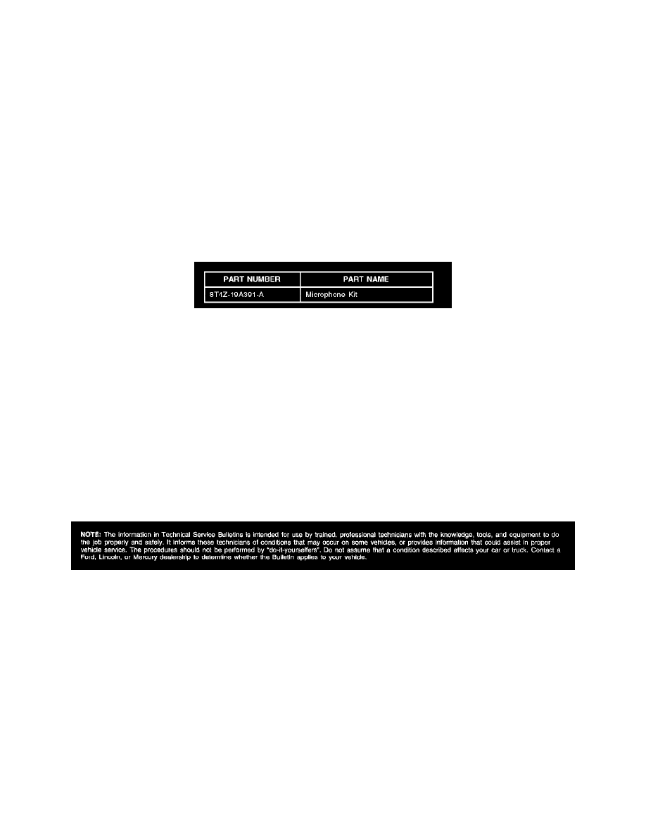
Parts Block
WARRANTY STATUS: Eligible Under Provisions Of New Vehicle Limited Warranty Coverage
IMPORTANT: Warranty coverage limits/policies are not altered by a TSB. Warranty coverage limits are determined by the identified causal part.
OPERATION
DESCRIPTION
TIME
MT100803
Use SLTS Operations If
Actual
Available; Claim Additional
Time
Diagnosis Or Labor
Performed As Actual Time
DEALER CODING
CONDITION
BASIC PART NO.
CODE
19A391
42
Disclaimer