
MKT FWD V6-3.7L (2010)
Variable Valve Timing Actuator: Description and Operation
VARIABLE CAMSHAFT TIMING (VCT) SYSTEM
Overview
The VCT system enables rotation of the camshaft(s) relative to the crankshaft rotation as a function of engine operating conditions. There are 4 types
of VCT systems.
-
Exhaust phase shifting (EPS) system - the exhaust cam is the active cam being retarded.
-
Intake phase shifting (IPS) system - the intake cam is the active cam being advanced.
-
Dual equal phase shifting (DEPS) system - both intake and exhaust cams are phase shifted and equally advanced or retarded.
-
Dual independent phase shifting (DIPS) system - where both the intake and exhaust cams are shifted independently.
All systems have 4 operational modes: idle, part throttle, wide open throttle (WOT), and default mode. At idle and low engine speeds with closed
throttle, the powertrain control module (PCM) determines the phase angle based on air flow, engine oil temperature and engine coolant temperature.
At part and wide open throttle the PCM determines the phase angle based on engine RPM, load, and throttle position. VCT systems provide reduced
emissions and enhanced engine power, fuel economy and idle quality. IPS systems also have the added benefit of improved torque. In addition, some
VCT system applications can eliminate the need for an external exhaust gas recirculation (EGR) system. The elimination of the EGR system is
accomplished by controlling the overlap time between the intake valve opening and exhaust valve closing. Currently, both the IPS and DEPS systems
are used.
The VCT system knocking and noise concerns are diagnosed in the diagnostic/repair information. For additional information, refer to the Engine,
Engine System - General Information. Verification of incorrect VCT phasing on a warm engine operating below 1500 RPM can be isolated using a
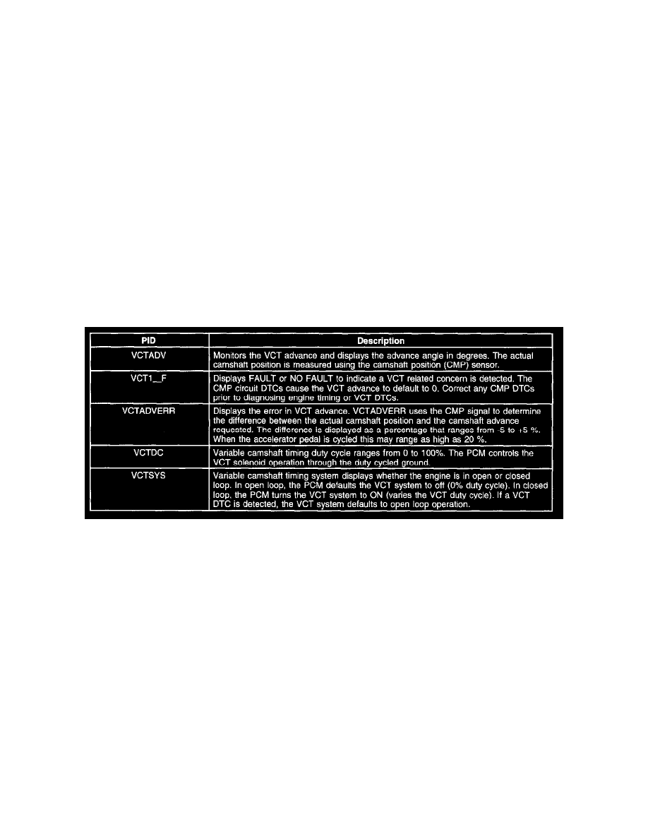
stethoscope and by monitoring the VCTADV, VCTADVERR and VCTDC PIDs using a scan tool. If the VCT phaser does not maintain correct valve
timing, low oil pressure or oil flow restrictions are primary possible causes. Verify correct oil pressure and flow, refer to the Engine, Engine System -
General Information.
Variable Camshaft Timing (VCT) System
The VCT system consists of an electric hydraulic positioning control solenoid, a camshaft position (CMP) sensor, and a trigger wheel. The CMP
sensor trigger wheel indicates the CMP signal for that bank. A crankshaft position (CKP) sensor provides the PCM with crankshaft positioning
information in 10 degree increments.
1. The PCM receives input signals from the intake air temperature (IAT), engine coolant temperature (ECT), engine oil temperature (EOT), CMP,
throttle position (TP), mass air flow (MAF), and CKP sensors to determine the operating conditions of the engine. At idle and low engine speeds
with closed throttle, the PCM controls the camshaft position based on ECT, EOT, IAT, and MAF. During part and wide open throttle, the
camshaft position is determined by engine RPM, load and throttle position. The VCT system does not operate until the engine is at normal
operating temperature.
2. The VCT system is enabled by the PCM when the correct conditions are met.
3. The CKP signal is used as a reference for CMP positioning.
4. The VCT solenoid valve is an integral part of the VCT system. The solenoid valve controls the flow of engine oil in the VCT actuator assembly.
As the PCM controls the duty cycle of the solenoid valve, oil pressure/flow advances or retards the cam timing. Duty cycles near 0% or 100%
represent rapid movement of the camshaft. Retaining a fixed camshaft position is accomplished by dithering (oscillating) the solenoid valve duty
cycle.
The PCM calculates and determines the desired camshaft position. It continually updates the VCT solenoid duty cycle until the desired position is
achieved. A difference between the desired and actual camshaft position represents a position error in the PCM VCT control loop. The PCM
disables the VCT and places the camshaft in a default position if a concern is detected. A related DTC is also set when the concern is detected.
5. When the VCT solenoid is energized, engine oil is allowed to flow to the VCT actuator assembly which advances or retards the camshaft timing.
One half of the VCT actuator is coupled to the camshaft and the other half is connected to the timing chain. Oil chambers between the 2 halves