
MKT FWD V6-3.7L (2010)
4. Inspect the manual pin to make sure it is correctly installed in the manual valve. If not, pull the valve body off the transaxle case. Correctly install
the manual pin in the manual valve and position the valve body in place.
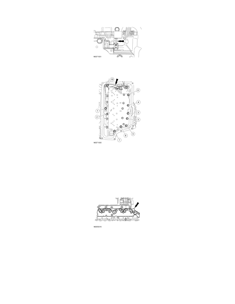
5. Install the TR sensor detent spring and the 10 valve body-to-case bolts. Tighten the bolts in the sequence shown.
-
Tighten to 12 Nm (106 lb-in).
6. NOTICE: Do not handle the solenoid body in the leadframe area or by the screens of the solenoid body filter or damage to the solenoid
body may occur.
NOTICE: Use care not to break the alignment tabs when installing the solenoid body filter. Damage to the transaxle will occur if the
solenoid body is not correctly aligned.
NOTICE: Make sure that the filter passage areas are clean of foreign material before installing the filter. Damage to the transaxle will
occur if the filter passages are not clean.
Install a new solenoid body filter assembly by pushing it straight down on to the alignment tabs.
7. NOTICE: Make sure not to pinch the Turbine Shaft Speed (TSS), Output Shaft Speed (OSS) or Transmission Range (TR) sensor wiring
harnesses when installing the solenoid body. Damage to the wiring harness will occur.
NOTE: Install the different length bolts in the locations noted during disassembly.
Install the solenoid body and the 11 bolts.
1. 42 mm (1.653 in) bolt
2. 63 mm (2.48 in) bolts
3. 80 mm (3.149 in) bolts
4. 95 mm (3.74 in) bolts