
MKX AWD V6-3.5L (2007)
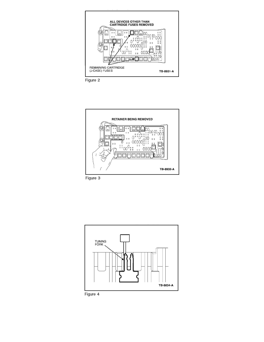
4. Remove all the mini fuses, relays and diodes (suggest taking a picture of the layout so install is easier). (Figure 2)
a. Do not remove the cartridge fuses from the BJB.
5. Remove the light gray retainer that the devices were plugged through. This will expose the terminals within the plastic housing. (Figure 3)
6. Locate the terminal cavities identified in procedure Step 3 that require repair. The tuning forks will be off center in relation to the plastic cavities or
open.
7. Insert a small flat blade screw driver/pick tool into the suspect tuning fork slot. The flat blade screw driver/pick tool width should be a maximum of
0.05" (1.25 mm) to provide access into the cavity. Tip dimensions were 0.04" x 0.04" (1 mm x 1 mm) with a 45 degree taper).
8. The small flat blade screw driver/pick tool should be inserted to the outside of the tuning fork leg between the tuning fork leg and the plastic wall of
the housing cavity. (Figure 4)