
MKZ AWD V6-3.5L (2008)
Driver/Vehicle Information Display: Initial Inspection and Diagnostic Overview
Inspection and Verification
INSPECTION AND VERIFICATION
1. Verify the customer concern.
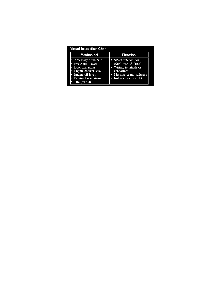
2. Visually inspect for obvious signs of mechanical or electrical damage.
Visual Inspection Chart
3. If an obvious cause for an observed or reported concern is found, correct the cause (if possible) before proceeding to the next step.
4. NOTE: Make sure to use the latest scan tool software release.
If the cause is not visually evident, connect the scan tool to the data link connector (DLC).
5. NOTE: The vehicle communication module (VCM) LED prove-out confirms power and ground from the DLC are provided to the VCM.
If the scan tool does not communicate with the VCM:
-
Check the VCM connection to the vehicle.
-
Check the scan tool connection to the VCM.
-
Refer to Information Bus (Module Communication Network), No Power To The Scan Tool, to diagnose no communication with the scan tool.
6. If the scan tool does not communicate with the vehicle:
-
Verify the ignition key is in the ON position.
-
Verify the scan tool operation with a known good vehicle.
-
Refer to Information Bus (Module Communication Network) to diagnose no response from the PCM.
7. Carry out the network test:
-
If the scan tool responds with no communication for one or more modules, refer to Information Bus (Module Communication Network).
-
If the network test passes, retrieve and record the continuous memory DTCs.
8. Clear the continuous DTCs and carry out the self-test diagnostics for the instrument cluster (IC).
9. If the DTCs retrieved are related to the concern, go to DTC Charts. See: Testing and Inspection/Diagnostic Trouble Code
Descriptions/Information and Message Center
10. If no DTCs related to the concern are retrieved, GO to Symptom Chart. See: Symptom Related Diagnostic Procedures
Principles of Operation
PRINCIPLES OF OPERATION
NOTE: The smart junction box (SJB) is also known as the generic electronic module (GEM).
The message center is an integral part of the instrument cluster (IC) that receives and acts upon much of the same information that is input and used to
operate the instrument cluster (IC) gauges, informational indicators, and warning indicators. The message center, located in the center of the instrument
cluster (IC), is a 2 line display. The message center electronic functions use both hardwired, and the controller area network (CAN) circuitry to transmit
and receive information.
Whenever conditions are present that require a warning message, the message center replaces the last selected display with the new warning display.
Once the message is reset or cleared, the message center returns to the last selected display. If multiple warning messages are present, the message center
displays each warning for approximately 4 seconds. Warning messages are also generally associated with other observable instrument cluster (IC)
indications. For example, when the LH front door is opened, the message center displays the message DRIVER DOOR AJAR along with the door ajar
warning indicator. This allows the message center to be a more informative supplement to the instrument cluster (IC) gauges and indicators.
It is very important to understand: