
Navigator 4WD V8-5.4L (2010)
2. Remove the generator. For additional information, refer to Charging System.
3. Disconnect the quick connect couplings and remove the crankcase ventilation tube. For additional information, refer to Fuel Delivery and Air
Induction.
4. Remove the bolt, loosen the clamp and remove the air intake resonator assembly.
5. Remove the 3 bolts and the Throttle Body (TB)-to-Air Cleaner (ACL) outlet tube adapter.
6. Disconnect the quick connect couplings and remove the PCV tube. For additional information, refer to Fuel Delivery and Air Induction.
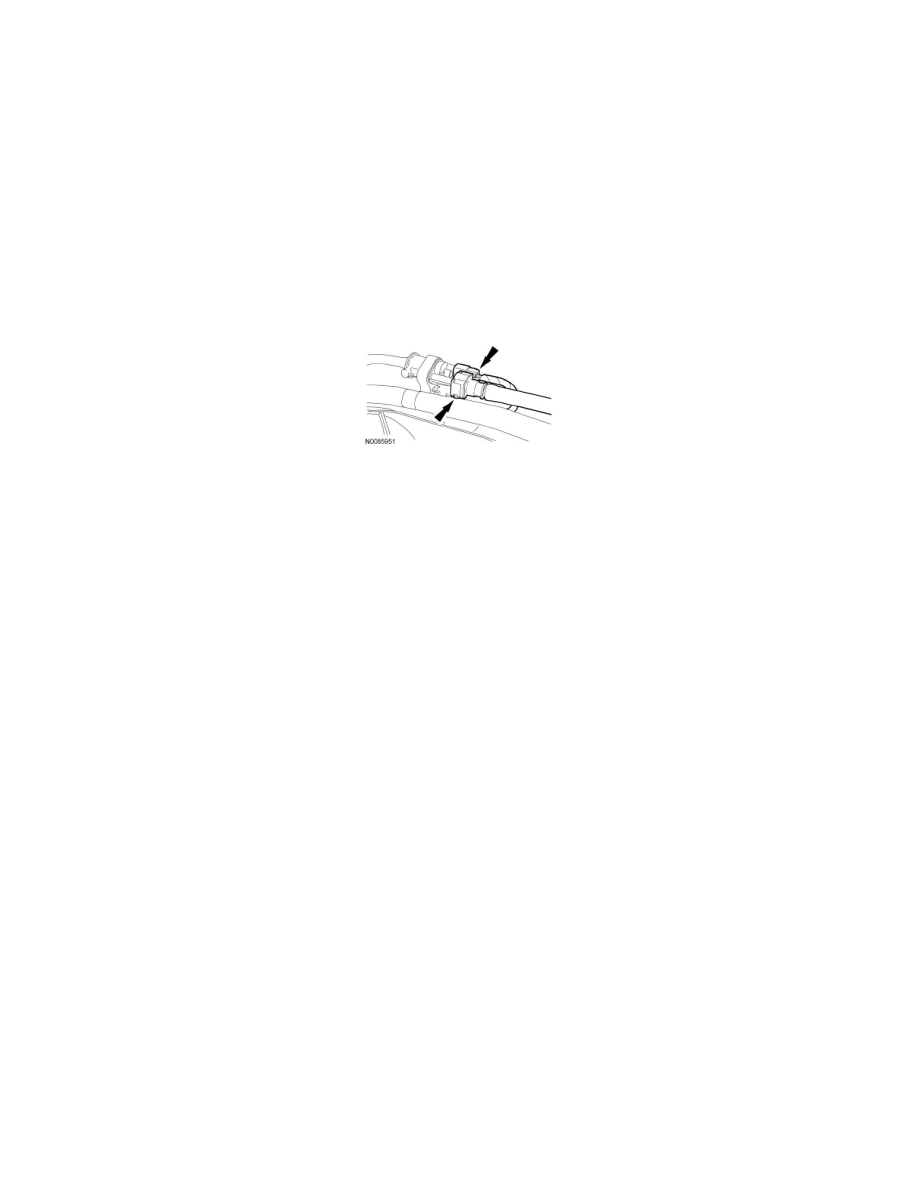
7. Disconnect the fuel supply tube quick connect coupling. For additional information, refer to Fuel Delivery and Air Induction.
8. Disconnect the electrical connector and the Evaporative Emission (EVAP) tube quick connect coupling from the EVAP canister purge valve. For
additional information, refer to Fuel Delivery and Air Induction.
9. Disconnect the upper radiator hose from the thermostat housing.
10. Disconnect the heater coolant hose from the coolant crossover manifold assembly.
11. Disconnect the 8 fuel injector electrical connectors.
12. Disconnect the Throttle Position (TP) sensor and Electronic Throttle Control (ETC) electrical connectors.
13. Disconnect the 4 LH ignition coil and the LH Variable Camshaft Timing (VCT) solenoid electrical connectors and detach the 2 engine wiring
harness retainers from the LH valve cover studs.
14. Disconnect the intake manifold vacuum tube from the brake booster vacuum hose.
15. NOTE: The intake manifold vacuum tube must be removed with the intake manifold as an assembly.
Disconnect the intake manifold vacuum tube from the LH valve cover studbolt and the support bracket at the rear of the LH cylinder head.
16. Remove the 10 intake manifold bolts.
17. NOTICE: Do not use metal scrapers, wire brushes, power abrasive discs or other abrasive means to clean the sealing surfaces. These tools
cause scratches and gouges which make leak paths. Use a plastic scraping tool to remove all traces of old sealant.
Remove the 3 bolts, the coolant crossover manifold assembly and discard the gaskets.
-
Clean and inspect the sealing surfaces with silicone gasket remover and metal surface prep. Follow the directions on the packaging.
18. NOTE: The intake manifold vacuum tube must be positioned under the engine wiring harness and removed with the intake manifold as an
assembly.
Position the intake forward to gain access to the wiring harness retainers.
19. Disconnect the 2 engine wiring harness retainers from the rear of the intake manifold.
20. Disconnect the Cylinder Head Temperature (CHT) sensor jumper harness electrical connector retainer.
21. NOTICE: Do not use metal scrapers, wire brushes, power abrasive discs or other abrasive means to clean the sealing surfaces. These tools
cause scratches and gouges which make leak paths. Use a plastic scraping tool to remove all traces of old sealant.
NOTE: The intake manifold vacuum tube must be positioned under the engine wiring harness and removed with the intake manifold as an
assembly.