
Navigator 4WD V8-5.4L (2010)
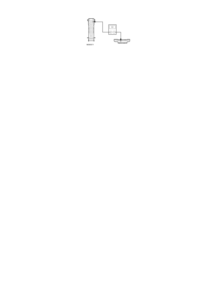
VDB07 (VT/OG), harness side.
-
Are the resistances less than 5 ohms?
Yes
CONNECT the negative battery cable. GO to I4.
No
REPAIR the circuit in question. CONNECT the negative battery cable. CLEAR the DTCs. REPEAT the network test with the scan tool.
-------------------------------------------------
I4 CHECK FOR CORRECT HVAC MODULE OPERATION
-
Disconnect all the HVAC module connectors.
-
Check for:
-
corrosion
-
damaged pins
-
pushed-out pins
-
Connect all the HVAC module connectors and make sure they seat correctly.
-
Operate the system and verify the concern is still present.
-
Is the concern still present?
Yes
INSTALL a new HVAC module. CLEAR the DTCs. REPEAT the network test with the scan tool.
No
The system is operating correctly at this time. The concern may have been caused by a loose or corroded connector.
-------------------------------------------------
Pinpoint Test J: The Liftgate/Trunk Module (LTM) Does Not Respond To The Scan Tool
Communications Network
Pinpoint Tests
Pinpoint Test J: The Liftgate/Trunk Module (LTM) Does Not Respond To The Scan Tool
Refer to Wiring Diagram Set 14, Module Communications Network for schematic and connector information. See: Diagrams/Electrical
Diagrams/Diagrams By Number
Refer to Wiring Diagram Set 109, Power Liftgate/Retractable Running Boards for schematic and connector information. See: Diagrams/Electrical
Diagrams/Diagrams By Number
Normal Operation
The Liftgate/Trunk Module (LTM) communicates with the scan tool through the Medium Speed Controller Area Network (MS-CAN).
This pinpoint test is intended to diagnose the following: