
Navigator 4WD V8-5.4L (2010)
-------------------------------------------------
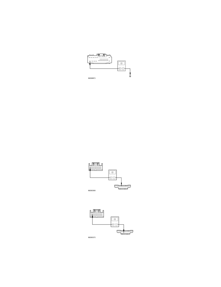
P2 CHECK THE DSM GROUND CIRCUIT FOR AN OPEN
-
Ignition OFF.
-
Disconnect: Negative Battery Cable.
-
Measure the resistance between the DSM C341b-24, circuit GD133 (BK), harness side and ground.
-
Is the resistance less than 5 ohms?
Yes
GO to P3.
No
REPAIR the circuit. CONNECT the negative battery cable. CLEAR the DTCs. REPEAT the network test with the scan tool.
-------------------------------------------------
P3 CHECK THE MS-CAN CIRCUITS BETWEEN THE DSM AND THE DLC FOR AN OPEN
-
Disconnect: DSM C341d.
-
Measure the resistance between the DSM C341d-10, circuit VDB06 (GY/OG), harness side and the Data Link Connector (DLC) C251-3, circuit
VDB06 (GY/OG), harness side.
-
Measure the resistance between the DSM C341d-9, circuit VDB07 (VT/OG), harness side and the DLC C251-11, circuit VDB07 (VT/OG),
harness side.
-
Are the resistances less than 5 ohms?
Yes
CONNECT the negative battery cable. GO to P4.
No