
Navigator 4WD V8-5.4L (2010)
If the vehicle is equipped with a Transmission Control Module (TCM), GO to Y26.
If the vehicle is not equipped with a TCM, REPAIR the circuit. CONNECT all modules. CONNECT the negative battery cable. CLEAR the DTCs.
REPEAT the network test with the scan tool.
-------------------------------------------------
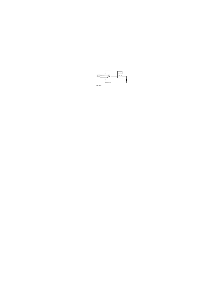
Y26 CHECK THE HS-CAN (+) AND HS-CAN (-) CIRCUITS FOR A SHORT TO GROUND WITH THE TCM DISCONNECTED
-
Disconnect: TCM C1548.
-
Measure the resistance between the DLC C251-6, circuit VDB04 (WH/BU), harness side and ground; and between the DLC C251-14, circuit
VDB05 (WH), harness side and ground.
-
Is the resistance less than 5 ohms?
Yes
CONNECT the negative battery cable. GO to Y34.
No
REPAIR the circuit. CONNECT all modules. CONNECT the negative battery cable. CLEAR the DTCs. REPEAT the network test with the scan tool.
-------------------------------------------------
Y27 CHECK FOR CORRECT PCM OPERATION
-
Disconnect all the PCM connectors.
-
Check for:
-
corrosion
-
damaged pins
-
pushed-out pins
-
Connect all the PCM connectors and make sure they seat correctly.
-
Operate the system and verify the concern is still present.
-
Is the concern still present?
Yes
INSTALL a new PCM. REFER to Computers and Control Systems. CONNECT all modules. CLEAR the DTCs. REPEAT the network test with the scan
tool.
No
The system is operating correctly at this time. The concern may have been caused by a loose or corroded connector. CONNECT all modules. CLEAR
the DTCs. REPEAT the network test with the scan tool.
-------------------------------------------------
Y28 CHECK FOR CORRECT VDM OPERATION
-
Disconnect all the VDM connectors.
-
Check for:
-
corrosion
-
damaged pins
-
pushed-out pins
-
Connect all the VDM connectors and make sure they seat correctly.
-
Operate the system and verify the concern is still present.