
Navigator 4WD V8-5.4L DOHC VIN A (2000)
Hazard Warning Switch: Testing and Inspection
Initial Inspection and Diagnostic Overview
1. Verify the customer concern by operating the multifunction or ignition switch.
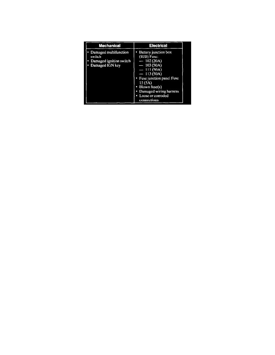
2. Visually inspect for obvious signs of mechanical and electrical damage.
3. If the concern remains after the inspection, connect the scan tool to the Data Link Connector (DLC) located beneath the instrument panel and
select the vehicle to be tested from the scan tool menu. If the scan tool does not communicate with the vehicle:
^
check that the program card is properly installed.
^
check the connections to the vehicle.
^
check the ignition switch position.
4. If scan tool still does not communicate with the vehicle, refer to the scan tool manual.
5. Perform the DATA LINK DIAGNOSTIC TEST. If the scan tool responds with:
^
CKT914, CKT915 or CKT70 = ALL ECUS NO RESP/NOT EQUIP, refer to Module Communications Network.
^
NO RESP/NOT EQUIP for GEM, go to Pinpoint Test A.
^
SYSTEM PASSED, retrieve and record the continuous Diagnostic Trouble Codes (DTCs), erase the continuous DTCs and perform self-test
diagnostics for the GEM.
6. If the DTCs retrieved arc related to the concern, go to the Generic Electronic Module (GEM) Diagnostic Trouble Code (DTC) Index to continue
diagnostics.
7. If no DTCs related to the concern are retrieved, proceed to Symptom Chart to continue diagnostics.
Generic Electronic Module (GEM) DTC Index