
Navigator 4WD V8-5.4L SOHC VIN 5 (2005)
2.
Check the Integrated Wheel End (IWE) on 4x4 units. Raise the front of the vehicle (wheels off the ground), engine running, and vehicle in 2WD
mode. The front half shafts should not turn when wheels are rotated by hand.
a.
If the IWE is functioning correctly, proceed to Step 3.
b.
If not, refer to Workshop Manual Section 308-07 and repair IWE first, then proceed to Step 3.
NOTE
THE PROCEDURE IN THIS TSB IS FAR MORE EFFECTIVE WHEN USING ROAD FORCE MEASUREMENT EQUIPMENT. ONLY USE A
STANDARD BALANCER AND MANUALLY CHECK RUN OUT WHEN ABSOLUTELY NECESSARY. VISIT WEBSITE
(WWW.G5P9700.COM) TO LOCATE THE NEAREST FACILITY THAT HAS THIS TYPE OF EQUIPMENT.
3.
If road force measurement equipment (Hunter GSP 9700, 9712, or equivalent) is available, proceed to Step 4. If not, balance the tires with a
standard balancer and use a dial indicator to locate and mark the high point of each tire's centerline radial runout. This will be used for the R1H
reading in the following steps. After marking the tires, proceed to Step 7.
NOTE
SUPPRESS ROUND OFF FUNCTION ON ROAD FORCE BALANCER TO ALLOW ACTUAL RESIDUALS TO BE DISPLAYED.
4.
Perform the road force measurement immediately after driving the vehicle. Remove the wheel cover and wheel assembly. Measure the road force
variation of all four tires. Measure and mark the tire HIGH road force variation point (R1H) on all four tires prior to dismounting them from the
road force measurement equipment. Balance as required to 0.35 oz (10g) or less of imbalance (check both two-plane and static). If any wheel
assembly measures more than 25 lbs R1H, then proceed to Step 5. If less than 25 lbs R1H, proceed to Step 6.
5.
Using the road force measurement equipment, determine the low spot of the wheel run out. Match high point force variation on the tire with the
low spot of wheel run out. If the wheel assembly is now acceptable, continue with rebalance. If not, replace the tire and recheck.
NOTE
THE SPARE TIRE SHOULD NOT BE USED AS A REPLACEMENT TIRE.
6.
Install the lowest R1H level tires on the front of the vehicle.
7.
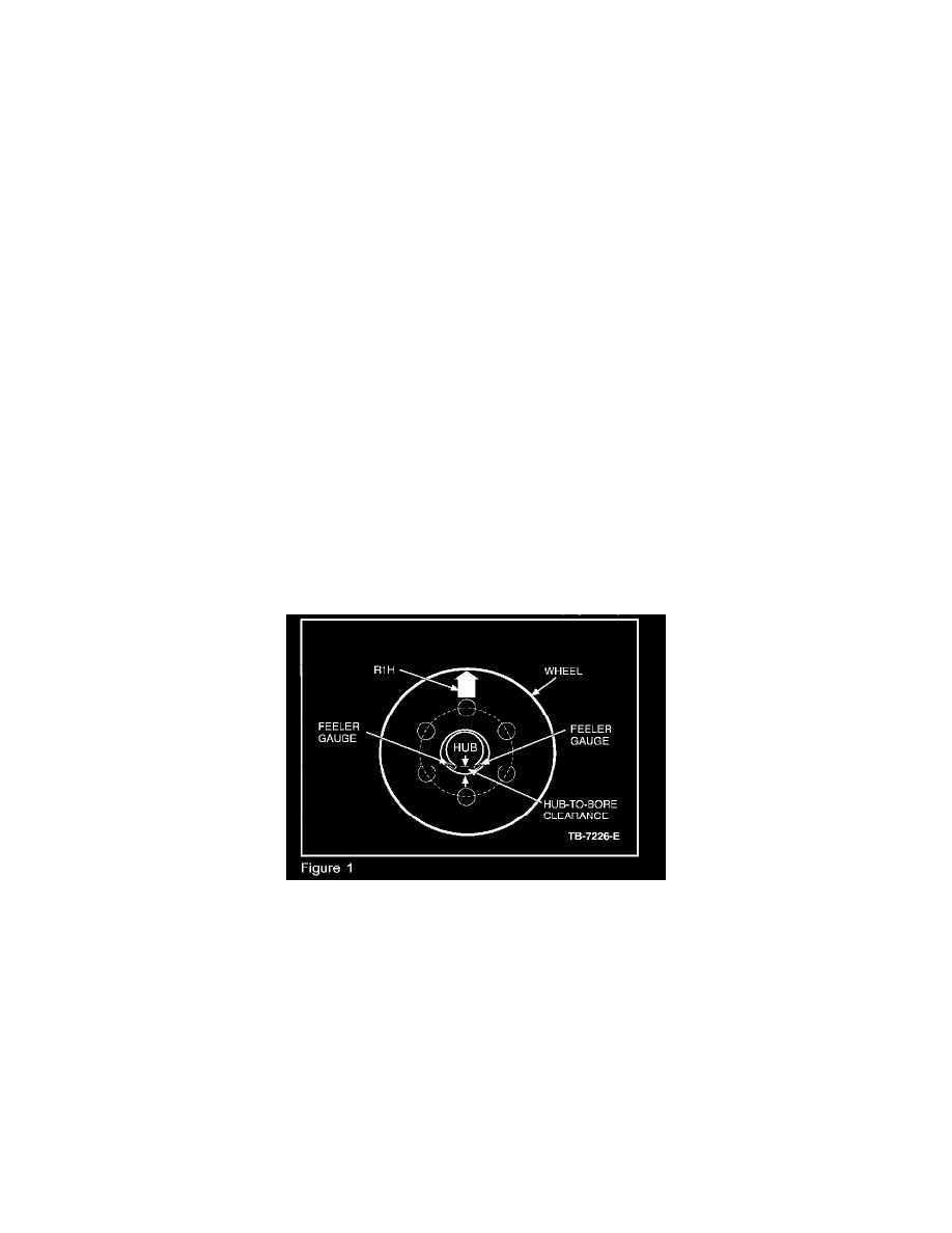
Position all tire/wheel assemblies on the hubs with the high R1H point, or high tire centerline radial run out, at the 12:00 position (Figure 2).
8.
Install the lug nuts and torque to 150 lb-ft (200 N.m).
9.
Using a flat feeler gauge, check the wheel hub-to-bore clearance to verify the largest gap is as close to the 6:00 position as possible (Figure 2). If
the largest gap is not located near the 6:00 position, remove the lug nuts and tire/wheel assembly, rotate the hub to a new position, and reinstall the
tire/wheel assembly again following Steps 7 and 8. Check again for the optimum 6:00 gap location.
10.
Road test vehicle to verify vehicle is corrected. If not corrected, proceed to Step 11.
11.
Replace the steering gear per the following vehicle and build date information.
NOTE
DO NOT REPLACE THE STEERING GEAR UNLESS NIBBLE CANNOT BE RESOLVED WITH TIRE/WHEEL BALANCE.
^
Expedition built from 3/17/2002-7/15/2002: