
Navigator 4WD V8-5.4L VIN 5 (2006)
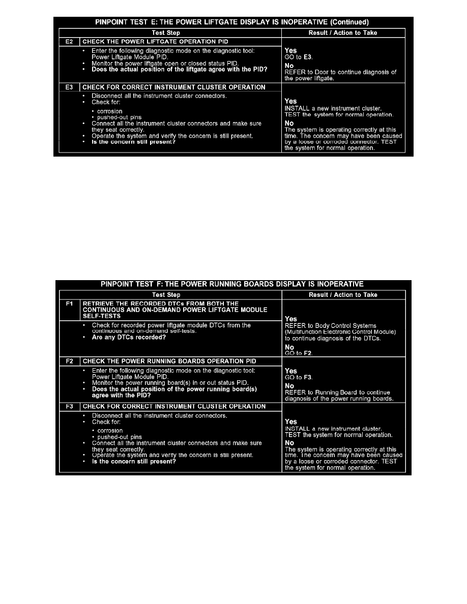
E2-E3
Normal Operation
The vehicle security module (VSM) sends a voltage reference signal through circuit 700 (WH/VT) to the power liftgate module. When the reference
signal loses the ground signal by the opening of the power liftgate, the VSM sends a signal over the communication network to the instrument cluster,
illuminating the power liftgate display.
Possible Causes
-
instrument cluster
-
power liftgate
Test F: The Power Running Boards Display Is Inoperative
PINPOINT TEST F: THE POWER RUNNING BOARDS DISPLAY IS INOPERATIVE
F1-F3
Normal Operation
The instrument cluster receives the running board status from the power liftgate module over the communication network. The retractable running
boards are controlled by the power liftgate module over the control circuits 1944 (BN/PK) (left side), and 1945 (VT/WH) (right side). The running
board motors are grounded through circuit 57 (BK). The retractable running board motors receive a ground signal from the power liftgate module to
deploy and an open signal to retract.
Possible Causes
-
instrument cluster
-
power running boards