
Town Car V8-281 4.6L SOHC (1991)
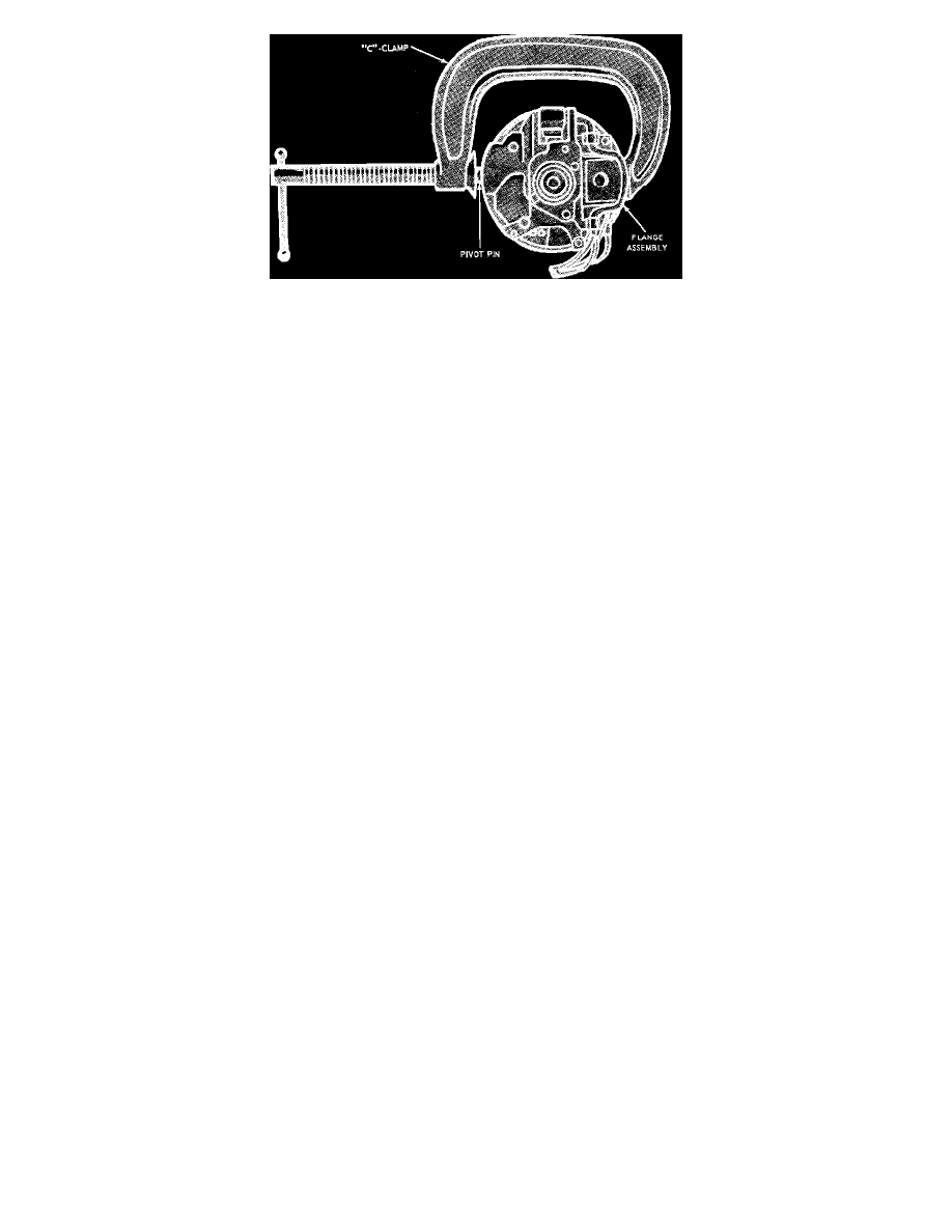
Fig. 29 Flange Assembly Pivot Pins Installation
Installation
1.
Position lock cylinder housing on upper steering column flange bracket. Place key in Start position to locate actuator interlock through clearance
hole in outer tube. Install and torque two bolts attaching lock cylinder housing to bracket to 12 to 20 ft. lbs.
2.
Install steering shaft assembly into steering column tube.
3.
Install upper casting assembly with tilt spring in position, over end of shaft and down into lock cylinder ears making certain lock lever is latched
into the top tilt position.
4.
Install tilt pivot pins through lower casting holes and into upper casting using a C-clamp, Fig. 29. Pivot pins must be flush with outer casing
surface.
5.
Install C-clip ring on upper shaft groove above bearing.
6.
Install upper bearing plate and conical spring. Press spring onto upper shaft until spring snaps into groove.
7.
Install turn signal switch and windshield wiper/washer switch.
8.
On column shift models, install shift cane assembly.
9.
On all except Ford & Mercury full size, install lower U-joint shaft assembly into lower steering shaft. Install attaching bolt with bolt head
against concave portion of tube. Torque nut and bolt to 35 to 45 ft. lbs.
10.
On all models, install steering column, then install steering wheel.
Models With Airbag
Removal
1.
Disarm airbag system as described under MAINTENANCE PROCEDURES/AIRBAG SYSTEM DISARMING.
2.
Remove upper and lower column shrouds.
3.
Peel back foam switch cover from turn signal switch.
4.
Disconnect two switch electrical connectors.
5.
Remove two self tapping screws that secure switch to lock cylinder housing and disengage switch from housing.
6.
Remove steering wheel.
7.
Disconnect airbag slip ring connector from column wiring harness. Before removing airbag slip ring/clockspring from steering shaft, the slip
ring/clockspring must be taped to prevent the slip ring/clockspring rotor from being turned accidentally and damaging the slip
ring/clockspring.
8.
Remove two screws attaching slip ring to retainer plate, then the slip ring.
9.
Remove upper bearing retainer plate.
10.
Remove and discard upper bearing retainer snap ring.
11.
Remove upper steering shaft bearing.
12.
Remove two bolts retaining lock cylinder housing to outer tube flange bracket, then rotate ignition key to Start position and pull actuator interlock
out of clearance hole in tube, lifting casting off upper steering shaft.
13.
Remove ignition lock drive gear.
INSTALLATION
1.
Install ignition lock drive gear and the actuator.
2.
Prick punch steering column upper shaft serration diameter enough to ensure an interference fit between bearing inner race and steering column
upper shaft.
3.
Place lock cylinder housing onto steering column flange bracket with upper steering shaft protruding through upper bearing.
4.
Turn ignition key to Start position to locate actuator interlock through clearance hole in outer tube, then install two bolts attaching lock cylinder
housing to bracket. Torque to 12-21 ft. lbs.
5.
Install upper steering shaft bearing.
6.
Install new snap ring in groove on upper shaft.
7.
Install bearing retainer plate.