
Town Car V8-302 5.0L (1987)
Valve Clearance: Adjustments
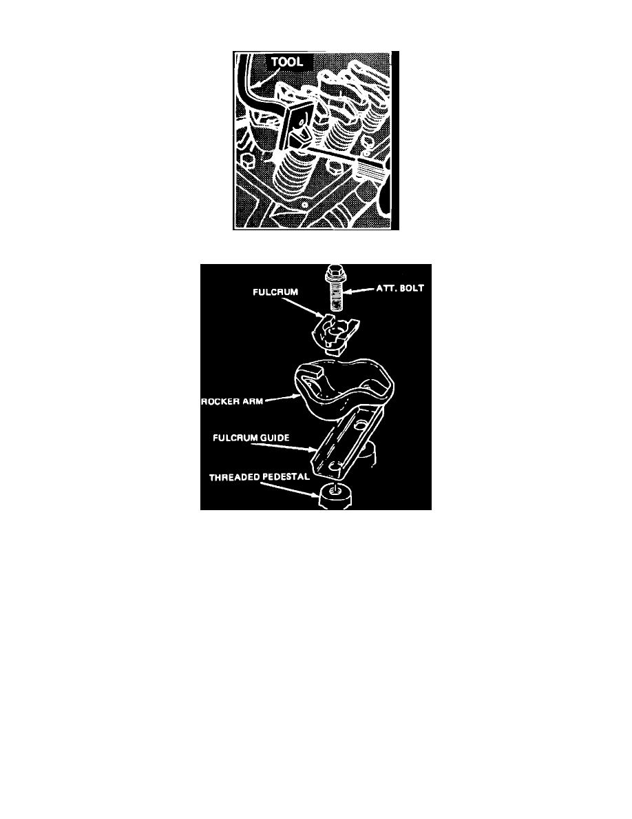
Fig. 6 Valve Clearance Adjustment
Fig. 5 Rocker Arm
V8-302
To eliminate the need of adjusting valve lash, a positive stop nut fulcrum bolt and seat is used on these engines, Fig. 9.
It is very important that the correct pushrod be used and all components be installed and torqued as follows:
1.
Position the piston of the cylinder being worked on at TDC of its compression stroke.
2.
Install rocker arm, fulcrum seat and oil deflector. Install fulcrum bolt and torque to 18---25 ft. lbs. A .060 inch shorter pushrod or a .060 inch
longer rod is available for service to provide a means of compensating for dimensional changes in the valve mechanism. Valve stem-to-rocker arm
clearance should be as specified, with the hydraulic lifter completely collapsed, Fig. 8. Repeated valve grind jobs will decrease this clearance to
the point that if not compensated for the lifters will cease to function. When checking valve clearance, if the clearance is less than the minimum,
the .060 inch shorter pushrod should be used. If clearance is more than the maximum, the .060 inch longer pushrod should be used. To check valve
clearance, proceed as follows:
1.
Mark crankshaft pulley at three locations, with number 1 location at TDC timing mark (end of compression stroke), number 2 location one half
turn (180°) clockwise from TDC and number 3 location three quarter turn clockwise (270°) from number 2 location.
2.
Turn the crankshaft to the number 1 location and check the clearance on the following valves:
a. V8-302: intake Nos. 1, 7 and 8; exhaust Nos. 1, 4 and 5.
b. V8-302 H.O.: intake Nos. 1, 4 and 8; exhaust Nos. 1, 3 and 7.
3.
Turn the crankshaft to the number 2 location and check the clearance on the following valves:
a. V8-302: intake Nos. 4 and 5; exhaust Nos. 2 and 6.
b. V8-302 H.O.: intake Nos. 3 and 7; exhaust Nos. 2 and 6.
4.
Turn the crankshaft to the number 3 location and check the clearance on the following valves:
a. V8-302: intake Nos. 2, 3 and 6; exhaust Nos. 3, 7 and 8.
b. V8-302 H.O.: intake Nos. 2, 5 and 6; exhaust Nos. 4, 5 and 8.