
Town Car V8-302 5.0L (1987)
wrench reading, the following formula must be used to determine torque. Torque (using tool T66P-3553-B, or equivalent) equals (length of torque
wrench x 72 ft. lbs.) ÷ (length of torque wrench + 5.5 inches).
3.
Install race nut screw and torque to 15---25 in. lbs.
4.
Place piston on bench with ball guide holes facing up. Insert worm shaft into piston so that first groove is in alignment with hole nearest to center
of piston, Fig. 6.
5.
Place ball guide into piston. Place balls in guide, turning worm clockwise (viewed from input end of shaft). If all balls have not been fed into guide
upon reaching right stop, rotate input shaft in one direction and then in the other while installing balls. After balls have been installed, do not rotate
input shaft or piston more than 3{1-2} turns off the right stop to prevent balls from falling out of circuit. The number of balls used varies with
the design of the piston.
6.
Securing guides to ball nut with clamp.
7.
Position new lube passage O-ring in counterbore of gear housing.
8.
Apply petroleum jelly to Teflon seal.
9.
Place a new O-ring on valve housing.
10.
Slide piston and valve into gear housing, being careful not to damage teflon seal.
11.
Align lube passage in valve housing with one in gear housing, and install but do not tighten attaching bolts at this time.
12.
Rotate ball nut so that teeth are in same plane as sector teeth. Tighten valve housing attaching bolts.
13.
Position sector shaft cover O-ring in gear housing. Turn input shaft as required to center piston.
14.
Apply petroleum jelly to sector shaft journal, then position sector shaft and cover into gear housing. Install identification tag and air conditioner
line mounting bracket (if so equipped) and two sector shaft cover bolts. Torque bolts to 55---70 ft. lbs.
15.
Attach an inch lb. torque wrench to input shaft and adjust mesh load as outlined previously.
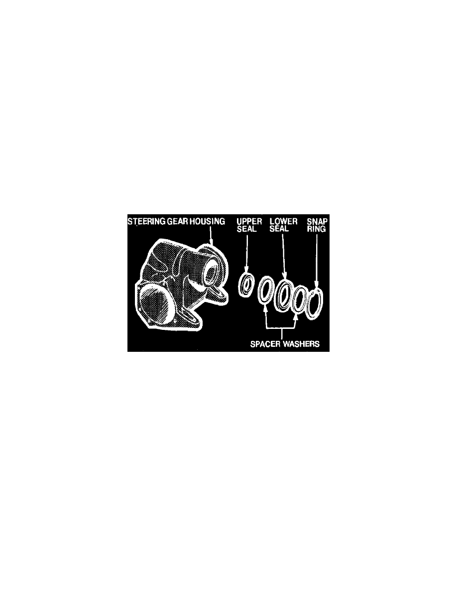
Gear Housing, Replace
Fig. 5 Steering gear housing disassembled
1.
Remove snap ring and spacer washer, Fig. 5, from lower end of gear housing.
2.
Remove lower seal from housing and lift spacer washer from housing.
3.
Remove upper seal in same manner.
4.
Dip both sector shaft seals in gear lube. Do not bottom seals against bearing. Press seals into housing only far enough to clear snap ring
groove.
5.
Position sector shaft inner seal (widest one) into housing with lip facing inward. Place a spacer washer on top of it.
6.
Place outer seal in housing with lip facing inward. Place spacer washer on top of it and press into place.
7.
Position snap ring in housing and press it in place to properly locate seals and engage snap ring in the groove.
Piston and Ball Nut, Replace