
Town Car V8-4.6L SOHC VIN W (1999)
point. Bulb goes on when the test point has voltage.
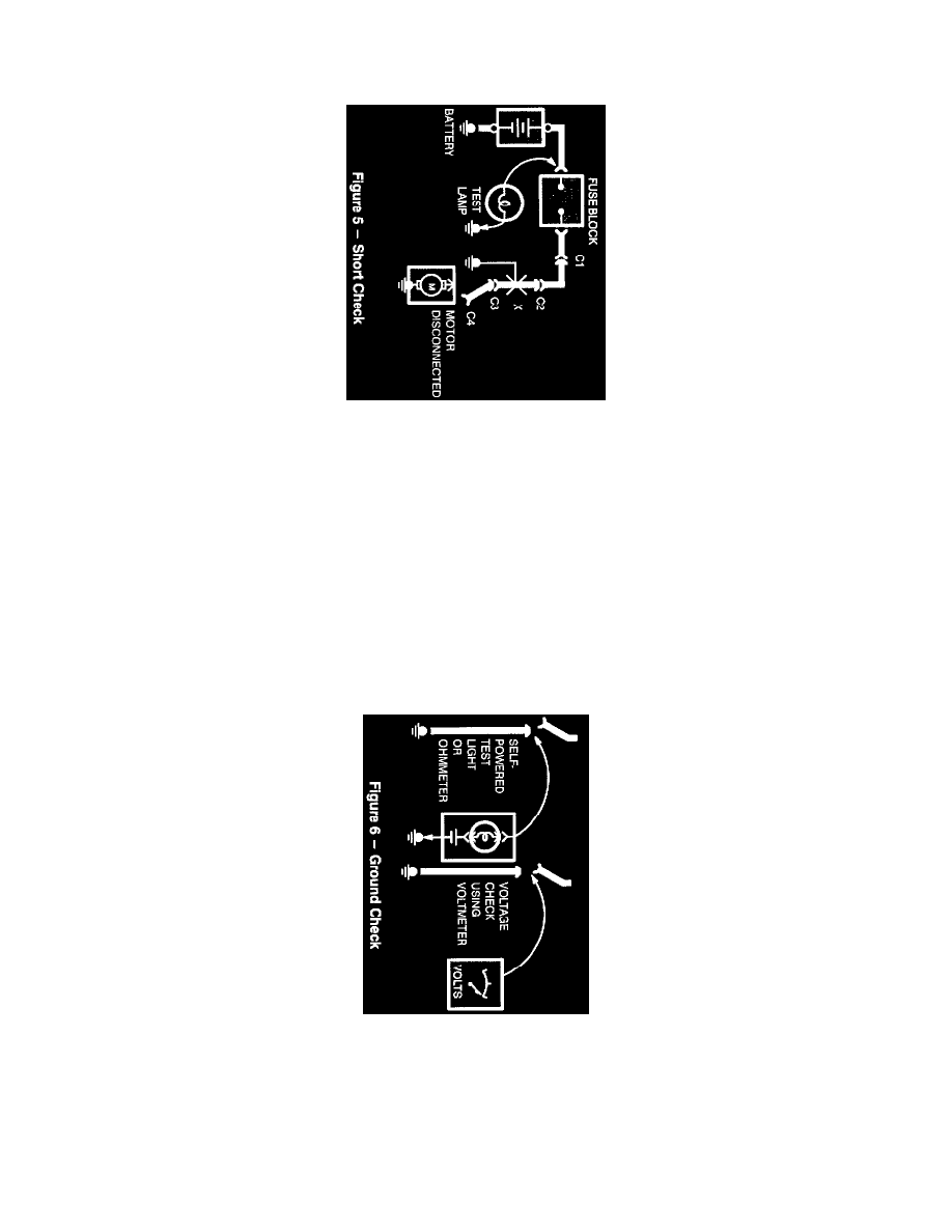
SHORT CHECK
A fuse that repeatedly blows is usually caused by a short to ground. It's important to be able to locate such a short quickly.
1. Turn off everything powered through the fuse.
2. Disconnect other loads powered through the fuse:
-
Motors: disconnect motor connector (Connector C4).
-
Lights: remove bulbs.
3. Turn Ignition Switch to RUN (if necessary) to power fuse.
4. Connect one Test Lamp lead to hot end of blown fuse. Connect other lead to ground. Bulb should glow, showing power to fuse. This step is
just a check to be sure you have power to the circuit)
5. Disconnect the test lamp lead that is connected to ground, and reconnect it to the load side of the fuse at the connector of the disconnected
component. (Connect the test lamp lead to connector C4).
-
If the Test Lamp is off, the short is in the disconnected component.
-
If the Test Lamp goes on, the short is in the wiring. You must find the short by disconnecting the circuit connectors, one at a time, until the
Test Lamp goes out. For example, with a ground at X, the bulb goes out when C1 or C2 is disconnected, but not after disconnecting C3.
This means the short is between C2 and C3.
GROUND CHECK
Turn on power to the circuit. Perform a Voltage Check between the suspected inoperative ground and the frame. Any indicated voltage means that the
ground is inoperative.
Turn off power to the circuit. Connect one lead of a Self-Powered Test Lamp or Ohmmeter to the wire in question and the other lead to a known
ground. If the bulb glows, the circuit ground is OK.
DIAGRAMS
These diagrams make it easy to identify common points in circuits. This knowledge can help narrow the concern to a specific area. For example, if
several circuits fail at the same time, check for a common power or ground connection (see Power and Ground Distribution Diagrams). If part of a