
Town Car V8-4.6L VIN V Flex Fuel (2006)
3. Turn the ignition switch to OFF.
4. At the central junction box (CJB), located below the LH side of the instrument panel, remove the cover and the restraints control module (RCM)
fuse 2 (10A) from the CJB. For additional information, refer to the Wiring Diagram Manual.
5. Turn the ignition ON and visually monitor the air bag indicator for at least 30 seconds. The air bag indicator will remain lit continuously (no
flashing) if the correct RCM fuse has been removed. If the air bag indicator does not remain lit continuously, remove the correct RCM fuse before
proceeding.
6. Turn the ignition OFF.
Warning: WARNING: To avoid accidental deployment and possible personal injury, the backup power supply must be depleted before
repairing or replacing any front or side air bag supplemental restraint system (SRS) components and before servicing, replacing, adjusting or
striking components near the front or side air bag sensors, such as doors, instrument panel, console, door latches, strikers, seats and hood
latches.
The 2 front impact severity sensors are located at the top and in front of each side of the radiator core support.
The side impact sensors (if equipped) are located at or near the base of the B-pillars.
To deplete the backup power supply energy, disconnect the battery ground cable and wait at least one minute. Be sure to disconnect auxiliary
batteries and power supplies (if equipped)
7. Disconnect the battery ground cable and wait at least one minute.
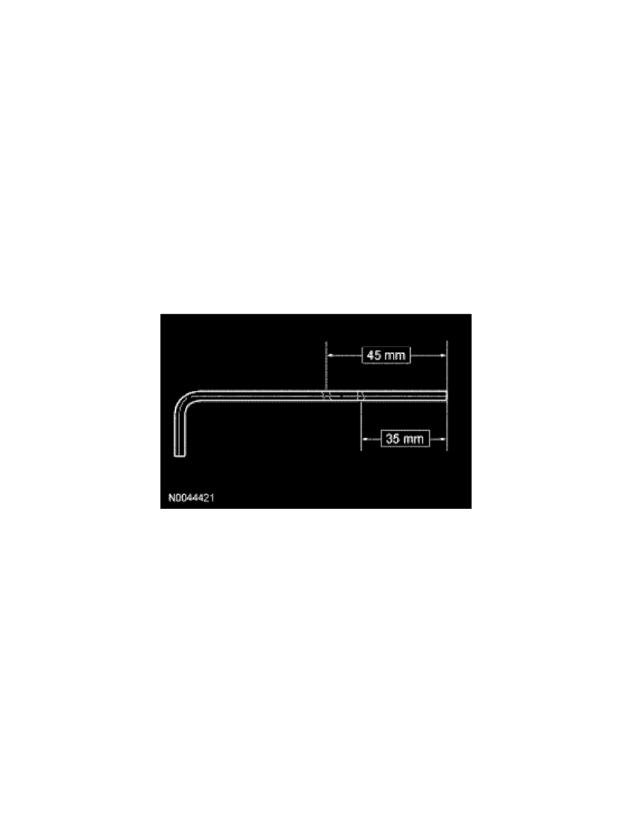
Note: A tool that has a blunt end, such as a 4.0 mm (0.15 in) Allen wrench, is better able to disengage the steering wheel spring clip from the driver air
bag module locking pins.
8. Using a 4 mm (0.15 in) Allen wrench or suitable tool, place 2 marks on the tool as an aid to remove the driver air bag module. One mark should be
approximately 35 mm (1.37 in) from the end of the tool with the second mark approximately 45 mm (1.77 in) from the end of the tool.
Note: The steering wheel rear cover has internal guides that assist in directing the tool to the correct location. Allow the steering wheel rear cover to
guide the tool, minimal force is needed.