
Town Car V8-4.6L VIN V Flex Fuel (2006)
C2-C3
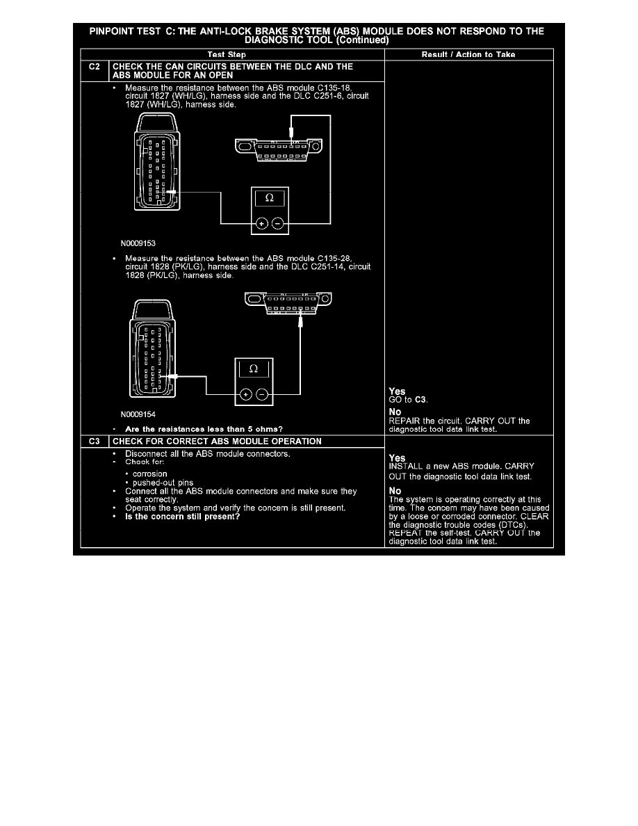
Normal Operation
The ABS module communicates with the diagnostic tool through the controller area network (CAN) circuits 1827 (WH/LG) and 1828 (PK/LG).
Check the CAN circuits between the ABS module C135 and the data link connector (DLC) C251. The total resistance values must not be more than 5
ohms. If the resistance is more than 5 ohms, there is an open in the CAN circuits, damage to the DLC C251, damage to the ABS module C135, or a
problem in the in-line connectors.
Possible Causes
-
CAN data plus circuit 1827 (WH/LG) open
-
CAN data minus circuit 1828 (PK/LG) open
-
ABS module C135
-
ABS module
Test D: The Lighting Control Module (LCM) Does Not Respond To The Diagnostic Tool
PINPOINT TEST D: THE LIGHTING CONTROL MODULE (LCM) DOES NOT RESPOND TO THE DIAGNOSTIC TOOL