
Town Car V8-4.6L VIN V Flex Fuel (2006)
Remove and discard the lower ball joint nut.
^
To install, tighten to 150 Nm (111 ft. lbs.).
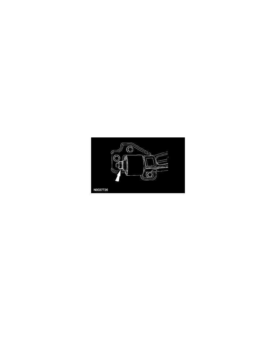
4. Remove the Shock absorber lower nut and the flag bolt.
^
Discard the nut and bolt.
^
To install, tighten to 225 Nm (166 ft. lbs.).
5. CAUTION: Do not remove the cam bolt at this time or damage to the steering bellows boot will result.
Remove the lower control arm cam bolt nut.
^
Discard the nut.
^
To install, tighten to 225 Nm (166 ft. lbs.).
6. Remove and discard the 3 lower arm bushing bracket bolts.
^
To install, tighten to 90 Nm (66 ft. lbs.).
7. Remove and discard the 2 steering rack gear nuts.
^
To install, tighten to 103 Nm (76 ft. lbs.).
8. Remove the 2 steering gear studs and move the steering gear upward to access the cam bolt.
^
To install, tighten to 30 Nm (22 ft. lbs.).
9. Remove the cam bolt and the lower arm.
10. NOTE: Snug the lower arm cam nuts and bolts, rear bushing nut and the Shock absorber lower nut and flag bolt. Do not tighten until the
installation procedure is complete and the weight of the vehicle is resting on the wheel and tire assemblies.
To install, reverse the removal procedure.
11. If a new lower control arm is being installed, tighten the bushing nut.
^
Vehicles with cast aluminum arm, to install tighten to 200 Nm (148 ft. lbs.).
^
Vehicles with stamped steel arm, to install tighten to 175 Nm (128 ft. lbs.).
12. Check and, if necessary align the front end.
Upper Arm
Upper Arm