
Town Car V8-4.6L VIN W (1997)
Hydraulic Control Assembly - Antilock Brakes: Service and Repair
Hydraulic Assembly
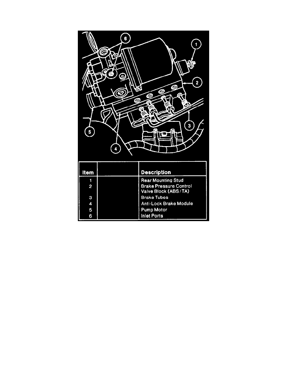
Fig. 114 Hydraulic Control Unit Removal
REMOVAL
1. Disconnect battery ground cable.
2. Remove engine air cleaner (ACL) and air cleaner outlet tube.
3. Disconnect 28-pin connector to ABS module wire harness.
4. Remove two tubes from inlet ports of the pump motor, three ABS system tubes and four ABS system/traction control tubes from outlet ports of
brake pressure control valve block. Plug each port to prevent brake fluid from spilling on paint and wiring.
5. Remove 13 mm nut retaining the hydraulic control unit to the mounting bracket. Tip the rear of the hydraulic control unit up and pull rearward to
slide the forward mounting pins out of the retaining grommets. Remove hydraulic control unit from
INSTALLATION
1. Insert hydraulic control unit mounting pins into front grommets on mounting bracket. Make sure hydraulic control unit is fully seated in bracket.
Install rear retaining nut. Tighten to 16-24 Nm (12-17 ft. lbs.).
2. Connect four tubes to outlet ports on side of brake pressure control valve block and two tubes to inlet ports on top of pump motor. Tighten tube
fittings to 14-24 Nm (11-17 ft. lbs.).
3. Connect 28-pin connector to ABS control module. Tighten bolt to 4-8 Nm (42 inch lbs.).