
Town Car V8-4.6L VIN W (1997)
20. Install bolts and stud bolts into RH valve cover. Tighten all bolts to 8-12 Nm (71-106 inch lbs.).
21. Install bolts and stud bolts into LH valve cover. Tighten all bolts to 8-12 Nm (71-106 inch lbs.).
22. Raise and support vehicle.
23. Connect fuel charging wiring to the power steering pump and oil pressure sensor.
24. Secure the fuel charging wiring to the oil filter adapter bracket.
25. Install oil pan gasket.
26. Install four oil pan-to-engine front cover bolts. Tighten in two steps in sequence shown:
a. Tighten to 20 Nm (15 ft. lbs.).
b. Tighten an additional 60°.
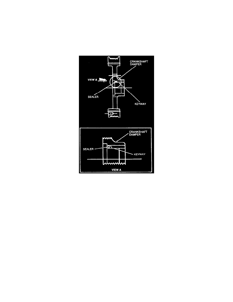
Crankshaft Pulley Keyway Silicone Gasket Sealant Application Locations
27. Clean crankshaft pulley, crankshaft and keyway sealing surfaces with Metal Surface Cleaner, to remove all residues that may interfere with the
sealer's ability to adhere.
28. Install crankshaft pulley bolt and crankshaft pulley retaining washer. Tighten in four steps:
Step 1 ... Tighten to 90 Nm (66 ft. lbs.).
Step 2 ... Loosen one complete turn (360°).
Step 3 ... Tighten to 50 Nm (36 ft. lbs.).
Step 4 ... Tighten an additional 90°.
29. Position power steering pump on engine and install four retaining bolts. Tighten to 20-30 Nm (15-22 ft. lbs.).
30. Lower vehicle.
31. Position fuel charging wiring on valve cover studs. Connect fuel charging wiring to the A/C clutch and crankshaft position sensor.
32. Connect 42-pin engine harness connector and eight pin transmission harness connector at power brake booster.
33. Install positive crankcase ventilation valve in RH valve cover and front evaporative emission hose.
34. Position positive battery cable harness on RH cylinder head.
35. Install bolt retaining battery cable bracket to cylinder head.
36. Connect front evaporative emission hose to evaporative emission canister purge valve. Position evaporative emission hose on valve cover studs.
37. Connect positive battery cable at power distribution box and harness (14516) and battery (10655).
38. Install water pump pulley and tighten bolts to 20-30 Nm (15-22 ft. lbs.).
39. Position ignition coil brackets and ignition wire and brackets (12280) assembly onto mounting studs.
40. Install two nuts and three bolts retaining ignition coil brackets to engine front cover. Tighten to 20-30 Nm (15-22 ft. lbs.).
41. Connect fuel charging wiring to both ignition coils radio ignition interference capacitor and camshaft position sensor.
42. Position air conditioner high-pressure line on RH ignition coil bracket and install nut.
43. Connect ignition wires to spark plugs. Refer to Powertrain Management. Install retainers onto valve cover studs.
44. Install accessory drive belt.