
Town Car V8-4.6L VIN W (1997)
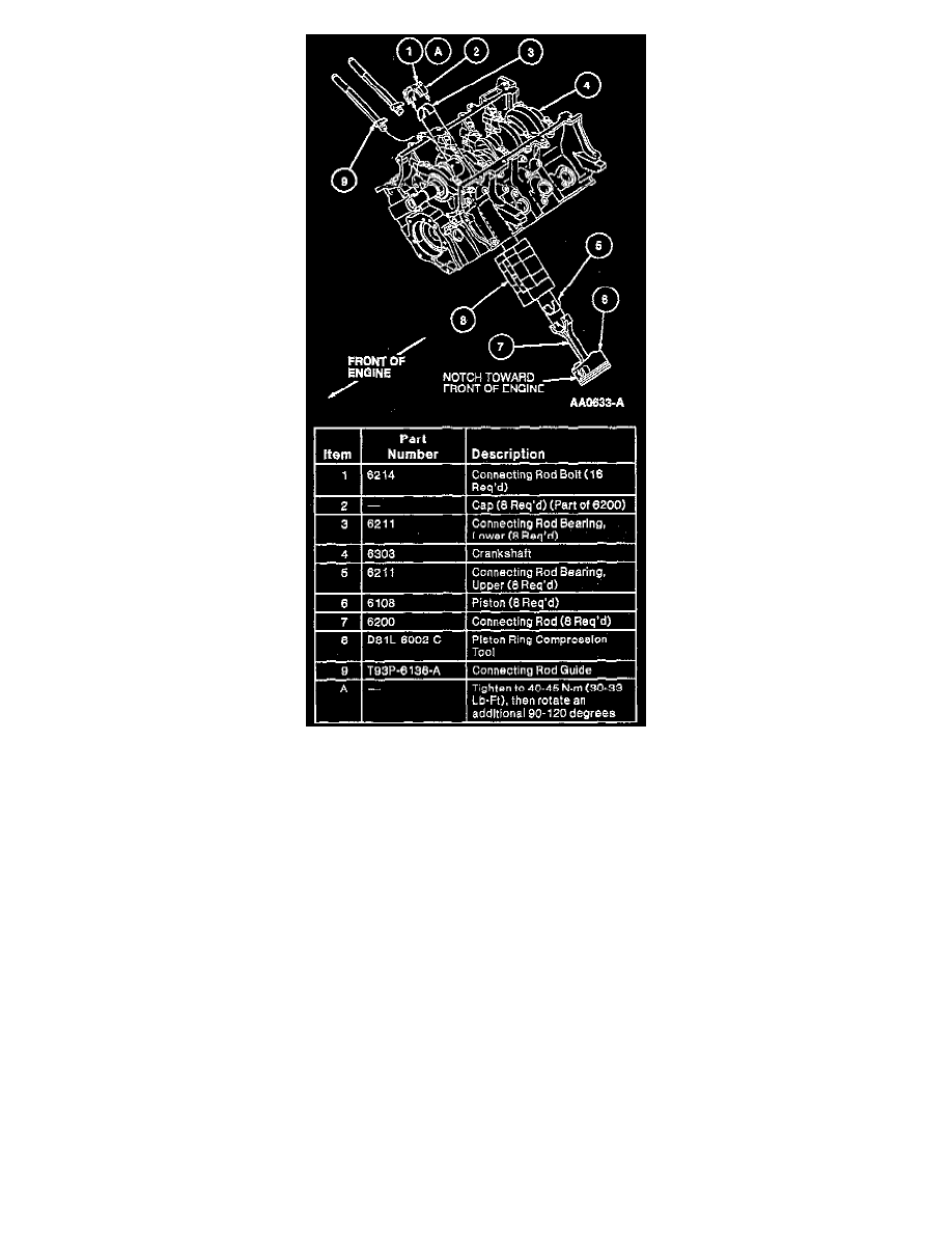
2. Turn crankshaft until the crankshaft throw is at bottom of stroke. Install correctly numbered piston and connecting rod assemblies with Piston Ring
Compressor D81 L-6002-C or equivalent and Connecting Rod Guide T93P-6136-A.
NOTE: Due to the use of a cracked connecting rod joint face surface, the connecting rod cap must be properly aligned to the connecting rod. The
connecting rod and connecting rod cap bearing tangs should be located on the same side of the connecting rod.
3. Alternately tighten connecting rod cap bolts in three steps:
a. Tighten to 20-25 Nm (15-18 ft. lbs.).
b. Tighten to 40-45 Nm (30-33 ft. lbs.).
c. Rotate bolts an additional 90-120°.
NOTE: After all connecting rod cap bolts are tightened to specification, rotate crankshaft to verify smooth operation.
4. Check connecting rod side clearance using Dial Indicator with Bracketry TOOL-4201-C or equivalent. Clearance should be 0.15-0.45 mm
(0.006-0.0177 inch). If side clearance is greater than maximum service limit of 0.50 mm (0.020 inch), replace connecting rods and/or crankshaft.
NOTE: Install new O-ring; then start all bolts on oil pump (6600) and oil pump screen cover and tube before tightening.
5. Install oil pump screen cover and tube.