
Town Car V8-4.6L VIN W (1997)
8. Tighten crankshaft main bearing cap adjusting screws in sequence to 9-11 Nm (80-97 inch lbs.).
9. Tighten main bearing cap side bolts in sequence to 19-23 Nm (14-17 ft. lbs.).
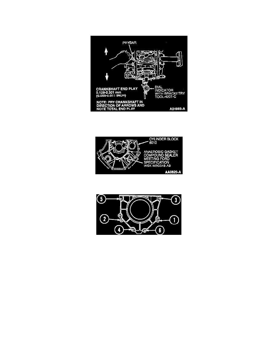
NOTE: Pry against number two main bearing cap.
10. Check crankshaft end play in both directions as shown.
NOTE: Crankshaft rear oil seal retainer must be installed and bolts tightened to specification within five minutes of sealer application.
11. Apply a 2.0 mm (0.08 inch) continuous bead of Anaerobic Gasket Compound Sealer or equivalent meeting Ford specification WSK-M2G348-A9
to cylinder block as shown.
Rear Oil Seal Retainer Tightening Sequence
12. Install crankshaft rear oil seal retainer to cylinder block and tighten six bolts in sequence to 8-12 Nm (71-106 inch lbs.).
13. Using Rear Seal Replacer Adapter T95P-6701-DH, Rear Main Seal Replacer T95P-6701-BH and Rear Slinger Replacer T95P-6701-CH, install
crankshaft rear oil seal and crankshaft oil slinger.
14. Turn crankshaft until the crankshaft throw is at bottom of stroke. Install upper connecting rod bearing onto connecting rod. Lubricate connecting
rod bearing and crankshaft with clean engine oil meeting Ford specification WSS-M2C910-A1.
CAUTION: Be sure not to scratch cylinder wall or crankshaft journal with connecting rod. Pull piston down until connecting rod bearing seats on
crankshaft journal.
NOTE: Due to the use of a cracked connecting rod joint face surface, the connecting rod cap must be properly aligned to the connecting rod. The
connecting rod and connecting rod cap bearing tangs should be located on the same side of the connecting rod.
15. Install connecting rod cap and lower connecting rod bearing and alternately tighten new connecting rod cap bolts in three steps:
a. Tighten to 20-25 Nm (15-18 ft. lbs.).
b. Tighten to 40-45 Nm (30-33 ft. lbs.).
c. Tighten an additional 90-120°. After installation, rotate crankshaft to make sure smooth operation.
16. Check connecting rod side clearance using Dial Indicator with Bracketry TOOL-4201-C or equivalent. Clearance should be 0.15-0.45 mm
(0.006-0.0177 inch). If side clearance is greater than maximum service limit of 0.50 mm (0.020 inch), replace connecting rods and/or crankshaft.