
Town Car V8-4.6L VIN W (1997)
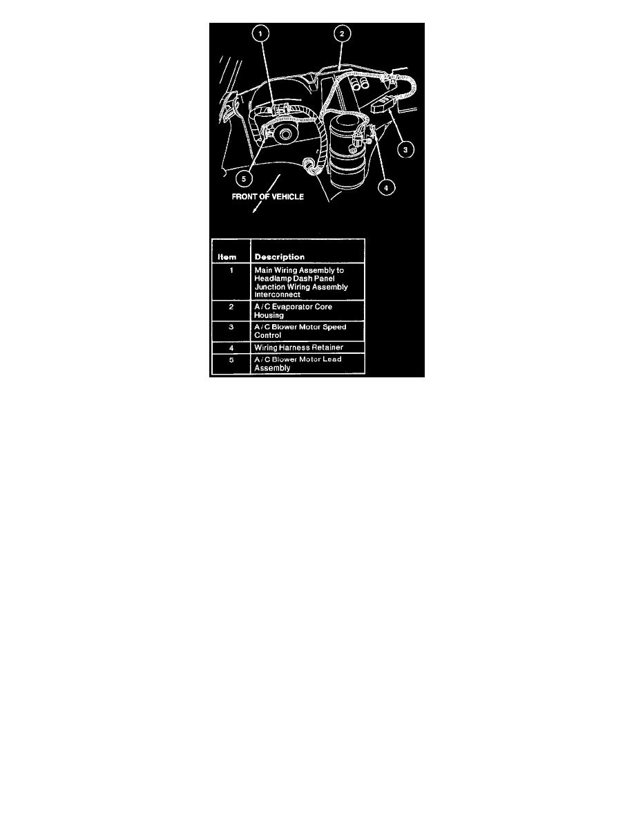
10. Disconnect A/C blower motor lead assembly from the main wiring harness and remove the hard-shell connector from the A/C blower motor speed
control and the A/C cycling switch.
11. Disconnect the main wire harness (which crosses the A/C evaporator core housing) at the hard shell connecting point and position it away from the
A/C evaporator core housing.
12. Remove instrument panel lower insulator from bottom of instrument panel on passenger side by disengaging four push pins and disconnecting
power point electrical connector.
13. Fold carpeting back on the RH side of the floor. Remove the bottom LH screw that supports the A/C recirculating air duct.
14. Remove RH front wheel and tire.
15. Remove retaining bolts from rear of RH fender apron. Position apron down in rear to improve access to A/C evaporator core housing.
16. From the engine side of the dash panel , remove the four nuts (one upper and two lower) from the three evaporator assembly mounting studs. Also
remove the two screws (one drill point and one sheet metal) from the top of the A/C evaporator core housing.
17. Pull the bottom of the A/C evaporator core housing assembly away from the dash panel to disengage the two bottom studs. Move the top of the
A/C evaporator core housing assembly away from the dash panel, disengaging it from the top stud, and maneuver the case up and over the fender
apron.
INSTALLATION
1. Position the A/C evaporator core housing assembly next to the dash panel by maneuvering it down past the tender apron.
2. Engage the two bottom dash panel studs into the A/C evaporator core housing assembly stud holes. Move the top of the A/C evaporator core
housing assembly toward the dash panel while engaging the top dash panel stud into the A/C evaporator core housing assembly stud hole.
3. Install, but do not tighten, the four stud nuts.
4. Install the two screws (one drill point and one sheet metal) and tighten to 2.5-3.2 N.m (23-28 Lb-in). Be careful to return the drill point screw to
the correct hole located on top of the A/C evaporator core housing and to the right of the blower motor. Tighten the three stud nuts previously
installed to 2.5-3.2 N.m (23-28 Lb-in).
5. Position the wire harness connector across the A/C evaporator core housing assembly and attach the various connectors.
6. Install A/C blower motor speed control.
7. Connect wire harness connectors to the blower motor and A/C blower motor speed control.
8. Install RH fender apron.
9. Install tire and wheel assembly.
10. Install radiator coolant recovery reservoir to tender apron with two retaining nuts tightened to 5.5-7.0 N.m (49-61 Lb-in).
11. Place the hose clamps onto the heater water hoses and carefully connect the hoses to the inlet and outlet heater core tubes. Refill coolant system.
12. Install purge valve mounting bracket to the cowl top extension with two retaining nuts.
13. Remove the plugs from the evaporator inlet tube and the condenser to evaporator tube and install new O-ring seals dipped in clean refrigerant oil.
Connect the condenser to evaporator tube to the evaporator inlet tube.