
Town Car V8-4.6L VIN W (1997)
Refrigerant Pressure Sensor / Switch: Description and Operation
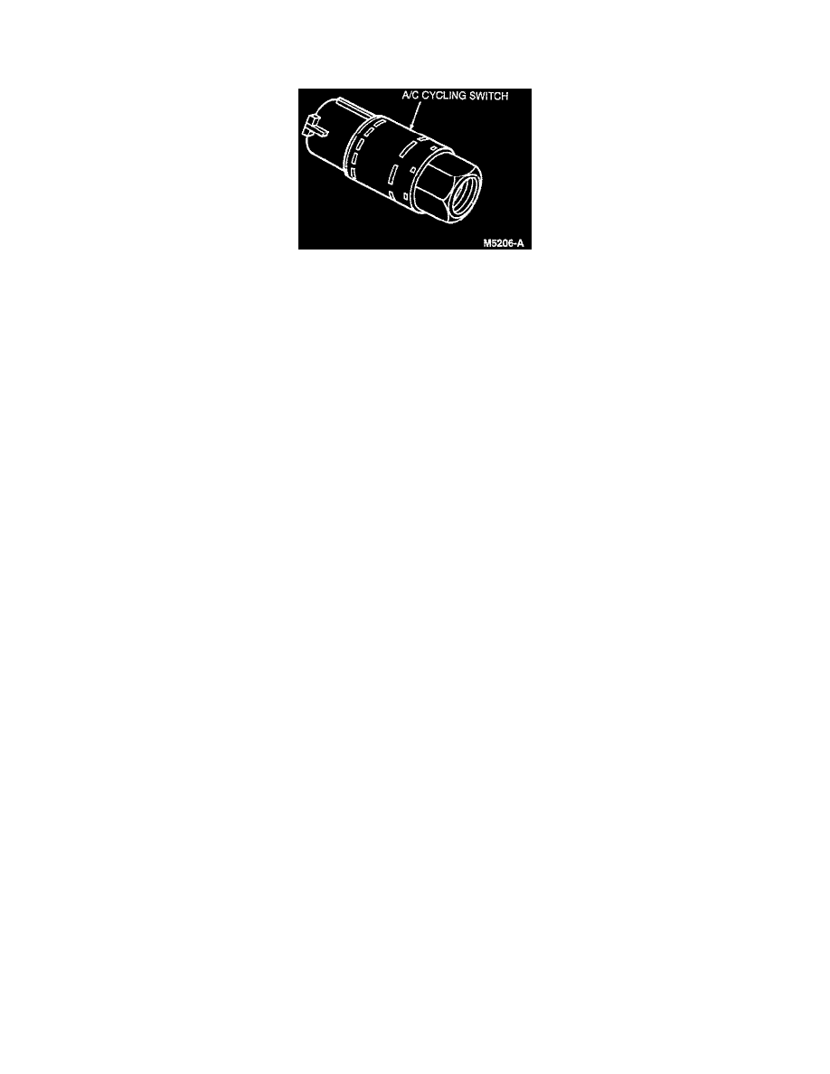
A/C Cycling Switch
The A/C cycling switch is mounted on a Schrader valve fitting on the top of the suction accumulator/drier.
^
A valve depressor, located inside the threaded end of the A/C cycling switch, presses in on the Schrader valve stem.
^
This allows the suction pressure inside the suction accumulator/drier to control the operation of the A/C cycling switch.
^
The electrical switch contacts will open when the suction pressure drops to 152-193 kPa (22-28 psi).
^
The contacts will close when the suction pressure increases to 276-324 kPa (40-47 psi).
^
Ambient temperature below approximately 7-10°C (45-50 °F), during cold weather seasons, prevents the A/C cycling switch contacts from
closing.
^
This is due to the pressure/temperature relationship of the refrigerant and the requirement of the system pressure to reach 276-324 kPa (40-47 psi)
to close the A/C cycling switch contacts.
^
These contacts control the electrical circuit to the A/C clutch field coil.
^
When the A/C cycling switch contacts close, the signal to energize the A/C clutch is sent to the constant control relay module.
^
The constant control relay module then supplies the voltage to energize the A/C clutch for A/C compressor operation.
^
When the A/C cycling switch contacts open, the constant control relay module opens the A/C clutch electrical circuit to de-energize the A/C
clutch. A/C compressor operation stops.
^
The A/C cycling switch will control the A/C evaporator core pressure at a point where the plate/fin surface temperature will be maintained slightly
above freezing.
^
This prevents A/C evaporator core icing and the blockage of airflow.