
Town Car V8-4.6L VIN W (1997)
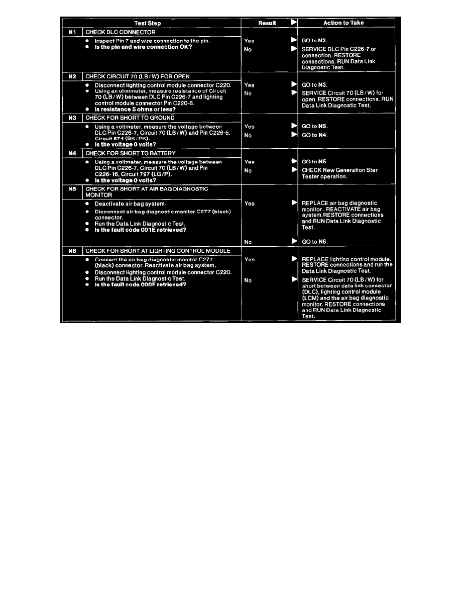
N1 - N6
Hookup and Vehicle Selection
Before any diagnostics can be performed on the communication system, use Rotunda New Generation Star Tester 007-00500 or equivalent to perform
the following steps:
1. Turn ignition switch OFF.
2. Select the appropriate program card for the vehicle.
3. With the New Generation Star Tester control unit facing away from you, insert the program card into the slot on the back. If you insert the card
incorrectly, New Generation Star Tester will not work.
4. Connect the New Generation Star Tester to the data link connector (DLC).
5. If using an alternate power hook up, plug the power cable into the cigar lighter socket or into the battery hookup adapter.
6. Turn ignition switch to RUN. New Generation Star Tester will perform an initialization, which checks the New Generation Star Tester memory
and verifies the vehicle interface module matches the program card software. If the screen displays an error message, Appendix C in the Rotunda
New Generation Star Tester Operator Handbook, System Messages.
7. Menu item "Vehicle and Engine Selection" is highlighted. Press trigger to select.
8. Rotate dial to menu item "Select New Vehicle Model and Year" and press trigger.
9. Select year, vehicle and appropriate engine by rotating dial to highlight selection, then press trigger to select. (If the selected vehicle is not
displayed on first row, then repeat steps 8 and 9. Otherwise, rotate dial to Selected Vehicle top row and press trigger.)
Data Link Diagnostic Test
1. Perform New Generation Star Tester Hookup and Vehicle Selection.
NOTE: The ignition switch must be in RUN position or test will fail. This test is used to verify the proper operation of communication circuit of
each module on the J1850 communication network or ISO 9141 communication network
2. Rotate dial to menu item "Diagnostic Data Link" and press trigger.
3. If results of Circuit 914 (+) = SYSTEM PASSED and Circuit 915 (-) = SYSTEM PASSED, then the J1850 communication network test passed. If
any other display is returned, then go to Communication Systems Diagnostics.
4. If results of Circuit 70 (LB/W) = SYSTEM PASSED, then the J1850 Communication Link Test passed. If any other display is returned, See: