
Zephyr V6-3.0L VIN 1 (2006)
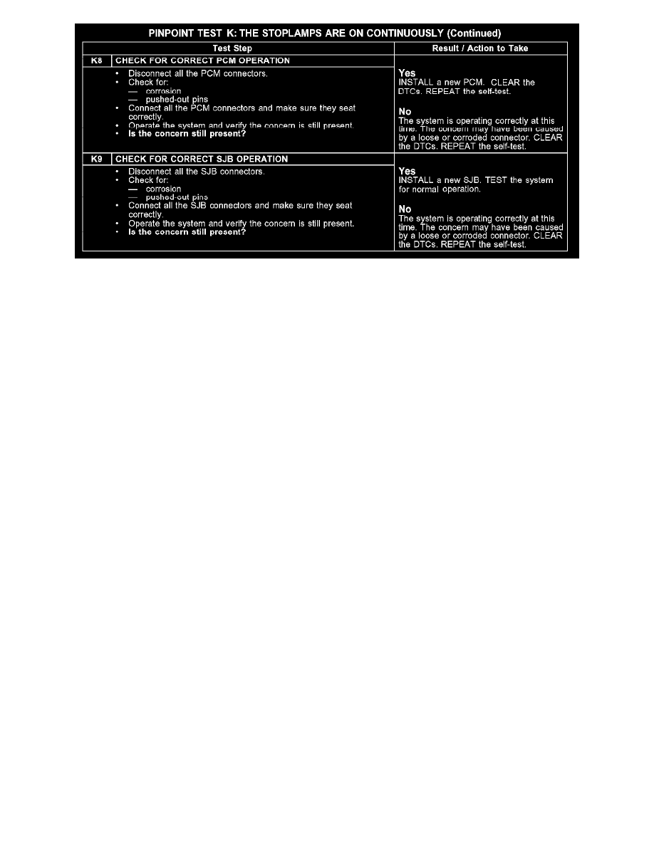
K8-K9
Normal Operation - Fusion
When the brake pedal is applied, the stoplamp switch routes voltage to the smart junction box (SJB) through circuit CCB08 (VT/WH). The voltage is
then routed out of the SJB to the high mounted stoplamp through circuit CLS17 (YE/GY). When the SJB detects the brake pedal applied, the SJB
provides voltage to the LH and RH rear stoplamps through circuit CLS18 (GY/BN) and circuit CLS19 (VT/OG), respectively.
Normal Operation - Milan, Zephyr
When the brake pedal is applied, the stoplamp switch routes voltage to the SJB through circuit CCB08 (VT/WH). The voltage is then routed out of the
SJB to the stoplamps through circuit CLS17 (YE/GY).
Possible Causes
-
Circuit CCB08 (VT/WH) short to voltage
-
Circuit CLS17 (YE/GY) short to voltage
-
Circuit CLS18 (GY/BN) short to voltage
-
Circuit CLS19 (VT/OG) short to voltage
-
Stoplamp switch
-
SJB
-
Powertrain control module (PCM)