
Zephyr V6-3.0L VIN 1 (2006)
27. CAUTION:
-
Do not install the driver air bag module electrical connectors by the locking buttons. Damage to the locking buttons can occur.
-
The driver air bag module electrical connector locking buttons must be in the released position when the connector is being installed,
or connector damage may occur.
-
The driver air bag module electrical connectors are unique and cannot be reversed when connected to the driver air bag module.
Match the electrical connector key to the keyway in the driver air bag module. Do not force the electrical connectors into the driver
air bag module.
With the locking buttons released, install the driver air bag module electrical connectors fully into the driver air bag module and seat the locking
buttons.
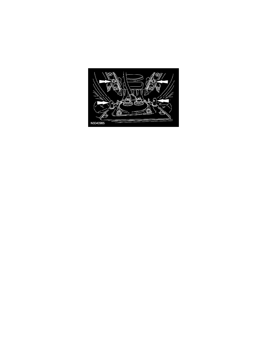
28. NOTE: Audible clicks will be heard when both wire clips are seated in the driver air bag module.
Align the driver air bag module locking pins to the steering wheel and, while pushing inward, seat the 2 driver air bag module locking pins in the
steering wheel wire clips.
-
When the 2 locking pins are seated in place, there should be an even gap between the driver air bag module trim cover and the steering wheel.
29. WARNING: The restraint system diagnostic tool is for restraint system service only. Remove from vehicle prior to road use. Failure to
remove the tool could result in injury and possible violation of vehicle safety standards.
Make sure all restraint system diagnostic tool(s) that may have been installed during the repair have been removed from the vehicle and all SRS
components are connected.
30. Turn the ignition switch from OFF to ON.
31. Install RCM fuse 25 (7.5A) to the SJB and close the cover.
32. WARNING: Be sure that nobody is in the vehicle and that there is nothing blocking or set in front of any air bag module when the
battery ground cable is connected.
Connect the battery ground cable.
33. Prove out the supplemental restraint system (SRS) as follows:
Turn the ignition switch from ON to OFF. Wait 10 seconds, then turn the ignition switch back to ON and visually monitor the air bag indicator
with the air bag modules installed. The air bag indicator will light continuously for approximately 6 seconds and then turn OFF. If an air bag SRS
fault is present, the air bag indicator will:
-
fail to light.
-
remain lit continuously.
-
flash at a 5 Hz rate (RCM not configured).
The air bag indicator might not light until approximately 30 seconds after the ignition switch has been turned from the OFF to the ON position.
This is the time required for the RCM to complete the testing of the SRS. If the air bag indicator is inoperative and a SRS fault exists, a chime will
sound in a pattern of 5 sets of 5 beeps. If this occurs, the air bag indicator and any SRS fault discovered must be diagnosed and repaired.
Clear all continuous diagnostic trouble codes (DTCs) from the RCM and occupant classification sensor (OCS) module using a diagnostic tool.