
3 L4-2.5L (2010)
Valve Clearance: Testing and Inspection
VALVE CLEARANCE INSPECTION [LF, L5]
1. Remove the battery cover. See: Starting and Charging/Battery/Service and Repair/Removal and Replacement
2. Disconnect the negative battery cable.
3. Remove the plug hole plate. See: Service and Repair/Removal and Replacement/Plug Hole Plate Removal/Installation
4. Disconnect the wiring harness.
5. Remove the ignition coils. See: Powertrain Management/Ignition System/Ignition Coil/Service and Repair
6. Remove the spark plugs. See: Tune-up and Engine Performance Checks/Spark Plug/Service and Repair
7. Remove the ventilation hose.
8. Remove the oil level gauge.
9. Remove the cylinder head cover. See: Timing Components/Timing Chain/Service and Repair
10. Remove the aerodynamic under cover No.2 and splash shield as a single unit. See: Body and Frame/Splash Guard/Service and
Repair/Aerodynamic Under Cover No.2 Removal/Installation See: Body and Frame/Splash Guard/Service and Repair/Splash Shield
Removal/Installation
11. Measure the valve clearance.
NOTE:
-
Make sure to note down the measured values for choosing the suitable replacement tappets.
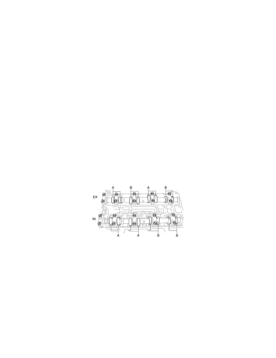
a. Turn the crankshaft clockwise so that the No.1 piston is at top dead center (TDC) of the compression stroke.
b. Measure the valve clearance at A in the figure.
Valve clearance [Engine cold]
-
IN: 0.22-0.28 mm {0.009-0.011 in}
-
EX: 0.27-0.33 mm {0.011-0.012 in}
c. If the valve clearance is out of the standard value, adjust it. See: Adjustments
d. Turn the crankshaft 360° clockwise so that the No.4 piston is at TDC of the compression stroke.
e. Measure the valve clearance at B in the figure.
Valve clearance [Engine cold]
-
IN: 0.22-0.28 mm {0.009-0.011 in}
-
EX: 0.27-0.33 mm {0.011-0.012 in}
f.
If the valve clearance is out of the standard value, adjust it. See: Adjustments
12. Install in the reverse order of removal.