
3 L4-2.5L (2010)
Body Control Module: Service and Repair
BODY CONTROL MODULE (BCM) REMOVAL/INSTALLATION
CAUTION:
-
When replacing the BCM, the configuration procedure must be performed before removing the BCM. Replacing the BCM without performing the
configuration procedure will result in system malfunction.
ATX
1. Perform the BCM configuration when replacing it. See: Testing and Inspection/Programming and Relearning/Body Control Module (BCM)
Configuration
2. Disconnect the negative battery cable.
3. Remove the following parts:
a. Front scuff plate (LH) See: Body and Frame/Interior Moulding / Trim/Scuff Plate/Service and Repair/Front Scuff Plate Removal/Installation
b. Front side trim (LH) See: Body and Frame/Interior Moulding / Trim/Trim Panel/Service and Repair/Front Side Trim Removal/Installation
c. Upper panel See: Body and Frame/Interior Moulding / Trim/Console/Service and Repair/Upper Panel Removal/Installation
d. Selector lever knob See: Transmission and Drivetrain/Automatic Transmission/Transaxle/Shifter A/T/Service and Repair/Automatic
Transaxle Shift Mechanism Removal/Installation
e. Shift panel See: Body and Frame/Interior Moulding / Trim/Console/Service and Repair/Shift Panel Removal/Installation
f.
Side wall See: Body and Frame/Interior Moulding / Trim/Dashboard / Instrument Panel/Service and Repair/Removal and Replacement/Side
Wall Removal/Installation
g. Console See: Body and Frame/Interior Moulding / Trim/Console/Service and Repair/Console Removal/Installation
4. Set the hood release lever out of the way. See: Body and Frame/Doors, Hood and Trunk/Hood/Hood Latch Release/Service and Repair
5. Remove the lower panel. (driver-side) See: Body and Frame/Interior Moulding / Trim/Dashboard / Instrument Panel/Service and Repair/Removal
and Replacement/Lower Panel Removal/Installation
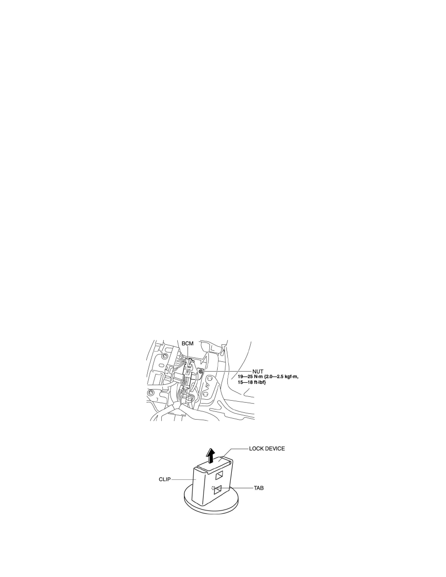
6. Remove the nut shown in the figure.
7. Pry off the lock device of the clip while pressing the tab in the position shown in the figure.
8. Rotate the clip in the direction of the arrow shown in the figure.