
3 L4-2.5L (2010)
Intermediate sensor specification
-
Below 1.0 V
3. Inspect the signal circuit for the intermediate sensor.
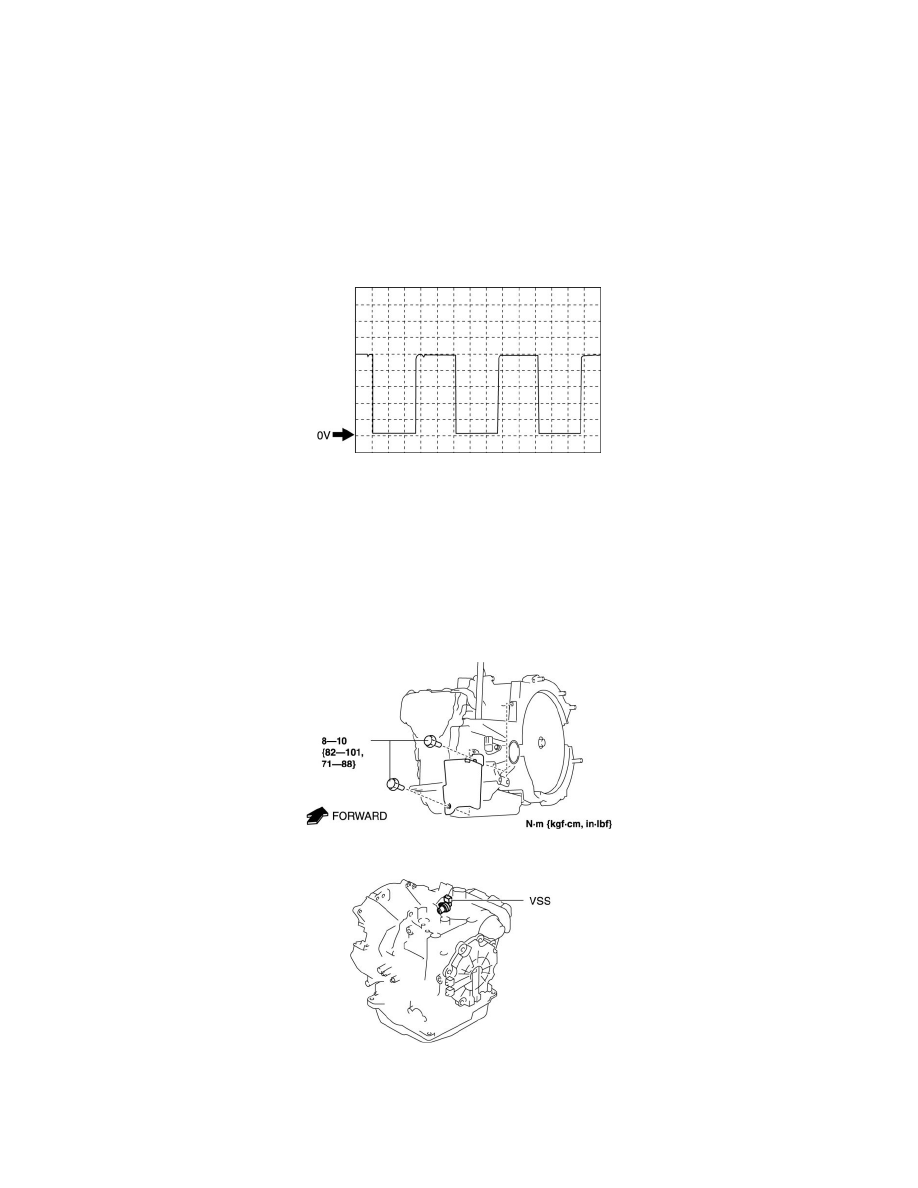
a. Connect the oscilloscope to the following TCM connector terminals and set it as below.
-
(+) lead: TCM terminal AC
-
(-) lead: battery negative terminal
-
Oscilloscope setting: 1 V/DIV (Y), 2 ms/DIV (X), DC range
b. Start the engine.
c. Measure the wave form when vehicle speed at 30 km/h {19 mph}.
-
If there is any malfunction, replace the intermediate sensor. See: Service and Repair/Intermediate Sensor Removal/Installation - FS5A-EL
Vehicle Speed Sensor (VSS) Inspection - FS5A-EL
VEHICLE SPEED SENSOR (VSS) INSPECTION [FS5A-EL]
On-Vehicle Inspection
1. Inspect the power supply circuit for the VSS.
a. Remove the insulator from the transaxle.
b. Disconnect the VSS connector.
c. Switch the ignition to ON (engine off).
d. Measure the voltage at VSS connector terminal A (harness-side).