
3 L4-2.5L (2010)
-
If there is any malfunction, repair wiring harness between VSS and TCM.
VSS specification
-
4.5-5.5 V
e. Switch the ignition to off.
f.
Connect the VSS connector.
2. Inspect the GND circuit for the VSS.
a. Switch the ignition to off.
b. Measure the voltage at intermediate sensor connector terminal C (harness-side).
-
If there is any malfunction, repair wiring harness between intermediate sensor and TCM.
Intermediate sensor specification
-
Below 1.0 V
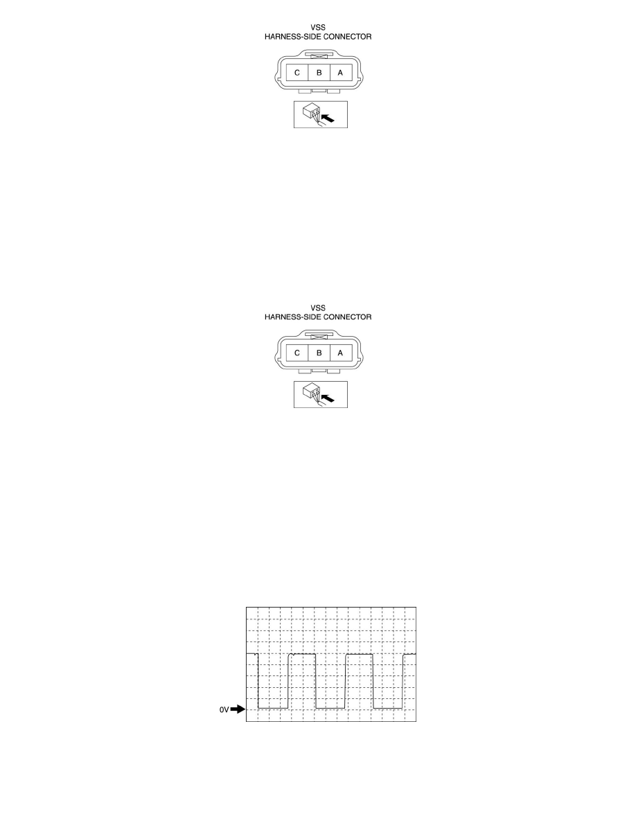
3. Inspect the signal circuit for the VSS.
a. Connect the oscilloscope to the following TCM connector terminals and set it as below.
-
(+) lead: TCM terminal Z
-
(-) lead: battery negative terminal
-
Oscilloscope setting: 1 V/DIV (Y), 2 ms/DIV (X), DC range
b. Start the engine.
c. Measure the wave form when vehicle speed at 30 km/h {19 mph}.
-
If there is any malfunction, replace the VSS. See: Powertrain Management/Computers and Control Systems/Sensors and Switches -
Computers and Control Systems/Vehicle Speed Sensor/Service and Repair