
323 L4-1600 1597cc (1986)
c. Connect ohmmeter between terminals E2 and VB. Resistance values should be 200-400 ohms.
d. Connect ohmmeter between terminals E2 and THA (intake air temperature sensor). At ambient temperatures of (-)4°F, resistance values
should be 10,000-20,000 ohms. At temperatures of 32°F, resistance should be 4,000-7,000 ohms. At temperatures of 68°F, resistance should
be 2,000-3,000 ohms. At temperatures of 104°F, resistance should be 900-1,300 ohms. At temperatures of 140°F, resistance should be
400-700 ohms.
e. Connect ohmmeter between terminals E1 and FC. Ohmmeter should read infinity.
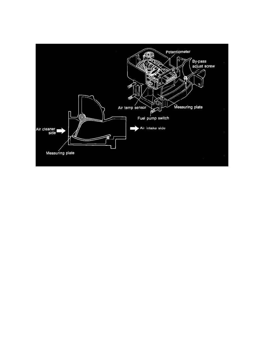
Fig. 3 Exploded View, Air Flow Meter
3.
Check operation of measuring plate, Fig. 3 as follows:
a. With measuring plate closed, check resistance between terminals E1 and FC (fuel pump switch). Ohmmeter should read infinity. Fully open
plate with a screwdriver, then observe ohmmeter. Resistance should be 0 ohms.
b. With measuring plate closed, check resistance between terminals E2 and VS. Resistance should be 20-400 ohms. Fully open plate as
described above and observe ohmmeter. Resistance should be 20-1,000 ohms.