
323 L4-1600 1597cc (1986)
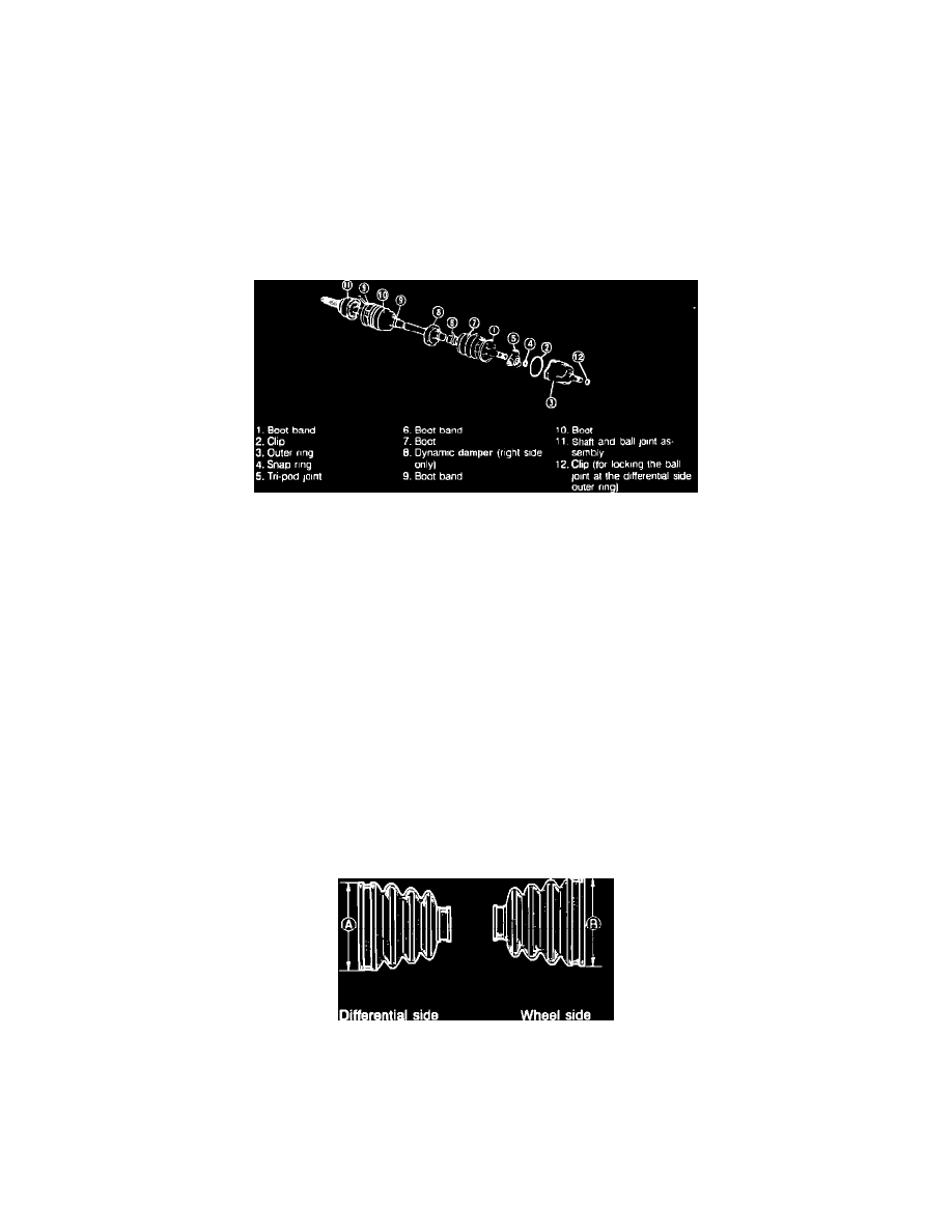
Fig. 10 Boot identification W/manual transaxle
4.
The shape of the ball joint boots at wheel side and differential side are different, do not intermix. On 1988 models exc. station wagon, ensure
dimensions A and B, Fig. 10, are as follows:
a. On non-turbo models, dimension A should be 3.29 inches (83.6 mm) and dimension B should be 3.56 inches (90.4 mm).
b. On turbo models, dimension A should be 3.76 inches (95.5 mm) and dimension B should be 3.64 inches (92.4 mm).
5.
Fill ball joint at wheel side with same amount of specified grease that had been wiped off.
6.
Align matching marks and install cage and inner ring on shaft, then install snap ring.
7.
Carefully fit boot in grooves in shaft and outer ring.
8.
Tighten boot band as follows. Always use new band. The band should be folded in direction opposite to forward revolving direction of
driveshaft.
a. Fold band back by pulling on end of band with pliers.
b. Lock end of band by bending locking clip.
Fig. 11 Exploded view of driveshaft W/automatic transaxle
Disassembly, Models W/Automatic Transaxle
Disassemble driveshaft in numerical order, Fig. 11, noting the following:
1.
When clamping shaft in vise, use wood against jaws to avoid damage.
2.
Do not allow dust or foreign matter to enter joint during disassembly or assembly.
3.
Do not disassemble ball joint at wheel side and do not wipe off grease unless necessary.
4.
Do not remove clip which is used to secure outer ring to ball joint at differential side unless necessary. If clip is removed, install new one.
5.
Remove boot, then remove clip with pliers.
6.
Paint alignment marks on tripod joint and outer ring.
7.
Remove tripod joint snap ring, then, using punch, place alignment marks on driveshaft end and tripod joint.
8.
Tap boss with hammer and rod to remove tripod joint. Do not tap on rollers.
Inspection, Models W/Automatic Transaxle
1.
Check for twisted or cracked driveshaft, replacing as necessary.
2.
Check for worn splines, replacing as necessary.
3.
Check for excessively loose joint, replacing as necessary.
4.
Check for cracked or damaged boots, replacing as necessary.
Fig. 10 Boot identification W/manual transaxle
Assembly, Models W/Automatic Transaxle
Reverse disassembly procedure to assemble, noting the following:
1.
On 1988 models, the shape of the ball joint boots at the wheel side and differential side are different. Do not intermix. Ensure dimension A, Fig.
10, is 2.39 inches (83.6 mm) and dimension B is 3.56 inches (90.4 mm).
2.
Install tripod joint as follows: