
5 L4-2.3L (2007)
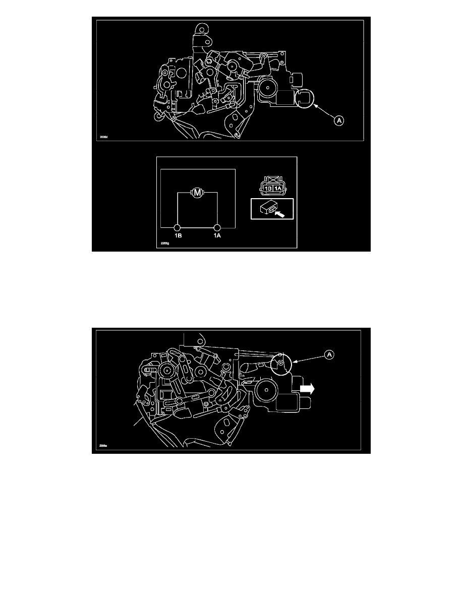
3. Check for battery voltage at the terminals of the lock actuator (A) when locking and unlocking the doors using the following diagram. You should get
battery voltage one way and ground the other way at each terminal.
a. If the voltage is NOT battery voltage, refer to MS3 online instructions or Workshop manual section 01-12 KEYLESS ENTRY SYSTEM
ON-BOARD DIAGNOSIS [KEYLESS ENTRY SYSTEM].
b. If the voltage is within specification, replace the lock actuator using the following steps.
1. Remove the remote controller, then remove the screw (A) which connects the remote controller and lock actuator.