
5 L4-2.3L (2007)
Knock Sensor: Testing and Inspection
KNOCK SENSOR (KS) INSPECTION[L3]
NOTE: Before performing the following inspection, make sure to follow the procedure as indicated in the troubleshooting flowchart.
Resistance Inspection
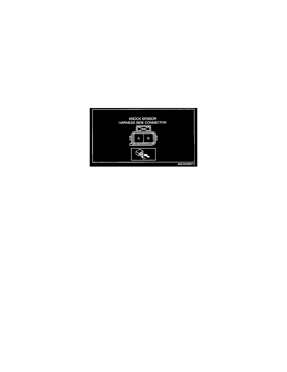
1. Disconnect the knock sensor connector.
2. Measure resistance between KS terminals A and B.
-
If not within the specification, replace the KS.
-
If the monitor item status/specification (reference) is not within the specification, even though the KS resistance is within the specification,
perform the "Circuit Open/Short Inspection".
Resistance
Approx. 4.87 megohms
Circuit Open/Short Inspection
1. Disconnect the PCM connector.
2. Inspect the following wiring harnesses for an open or short circuit. (Continuity inspection)
Open circuit
-
If there is no continuity, there is an open circuit. Repair or replace the wiring harness.
-
Knock sensor terminal A and PCM terminal 2Q
-
Knock sensor terminal B and PCM terminal 2R
Short circuit
-
If there is continuity, there is a short circuit. Repair or replace the wiring harness.
-
Knock sensor terminal A and power supply
-
Knock sensor terminal A and body ground
-
Knock sensor terminal B and power supply
-
Knock sensor terminal B and body ground