
5 L4-2.3L (2007)
Engine Control Module: Testing and Inspection
Using SST (M-MDS)
Using SST (M-MDS)
NOTE: PIDs for the following parts are not available on this model. Go to the appropriate part inspection.
-
CMP sensor (See CAMSHAFT POSITION (CMP) SENSOR INSPECTION [L3].) See: Computers and Control Systems/Camshaft
Position Sensor/Testing and Inspection/Component Tests and General Diagnostics
-
Main relay (See RELAY INSPECTION.)
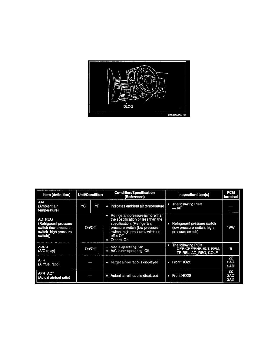
1. Connect the SST (M-MDS) to the DLC-2.
2. Turn the ignition switch to ON position.
3. Measure the PID value.
-
If PID value is not within the specification, follow the instructions in Action column.
NOTE:
-
The PID/DATA MONITOR function monitors the calculated value of the input/output signals in the PCM. Therefore, an output device
malfunction is not directly indicated as a malfunction of the monitored value for the output device. If a monitored value of an output device
is out of specification, inspect the monitored value of the input device related to the output control.
-
The simulation items that are used in the ENGINE CONTROL SYSTEM OPERATION INSPECTION are as follows.
- ACCS, ALTF, ARPMDES, EVAPCP FAN_DUTY, FP FUELPW1, GENVDSD, HTR11, HTR12, IMRC, IMTV, INJ_1, INJ_2, INJ_3,
INJ_4, SEGRP, test, VT DUTY1 Wt