
6 L4-2.5L (2010)
Information Bus: Initial Inspection and Diagnostic Overview
FOREWORD [MULTIPLEX COMMUNICATION SYSTEM]
-
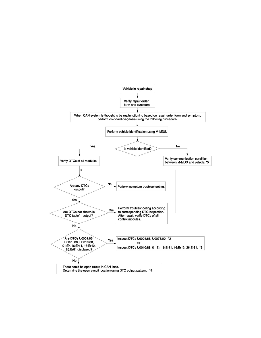
If the CAN system is considered to be the cause of the malfunction based on the repair order form and the malfunctioning symptom, follow the.
-
DTCs are also output due to a control module or sensor malfunction, or incorrect power supply. Verify the output DTCs and first inspect the DTCs
not shown in See: Testing and Inspection/Diagnostic Trouble Code Descriptions/DTC Table - Multiplex Communication System.
-
If there is an open circuit in the communication lines, it is possible that signal error DTCs may be output in addition to communication error
DTCs. Perform See: Body and Frame/Body Control Systems/Testing and Inspection/Component Tests and General Diagnostics/Determining
Malfunctioning Part (HS-CAN) - Multiplex Communication System, See: Body and Frame/Body Control Systems/Testing and
Inspection/Component Tests and General Diagnostics/Determining Malfunctioning Part (MS-CAN) - Multiplex Communication System if the
communication error and signal error DTCs are output simultaneously.
Troubleshooting Procedure
*1
See: Testing and Inspection/Diagnostic Trouble Code Descriptions/DTC Table - Multiplex Communication System
*2
See: Testing and Inspection/Diagnostic Trouble Code Tests and Associated Procedures/U Code Charts/U0001
*3
See: Testing and Inspection/Diagnostic Trouble Code Tests and Associated Procedures/U Code Charts/U0010
*4
See: Body and Frame/Body Control Systems/Testing and Inspection/Component Tests and General Diagnostics/Determining
Malfunctioning Part (HS-CAN) - Multiplex Communication System / See: Body and Frame/Body Control Systems/Testing and
Inspection/Component Tests and General Diagnostics/Determining Malfunctioning Part (MS-CAN) - Multiplex Communication System