
6 L4-2.5L (2010)
Valve Clearance: Testing and Inspection
VALVE CLEARANCE INSPECTION [L5]
1. Disconnect the negative battery cable.
2. Remove the plug hole plate. See: Engine, Cooling and Exhaust/Engine/Service and Repair/Removal and Replacement/Plug Hole Plate
Removal/Installation
3. Remove the ignition coils. See: Ignition System/Ignition Coil/Service and Repair
4. Remove the ventilation hose. See: Engine, Cooling and Exhaust/Engine/Intake Manifold/Service and Repair
5. Disconnect the camshaft position (CMP) sensor connector.
6. Disconnect the oil control valve (OCV) connector.
7. Remove the cylinder head cover. See: Engine, Cooling and Exhaust/Engine/Timing Components/Timing Chain/Service and Repair
8. Set the front mudguard (RH) out of the way. See: Body and Frame/Spoilers, Flaps, and Air Dams/Mud Flap/Service and Repair
9. Remove the splash shield (RH).
10. Measure the valve clearance.
NOTE:
-
Make sure to note down the measured values for choosing the suitable replacement tappets.
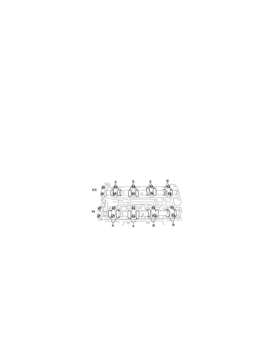
a. Turn the crankshaft clockwise so that the No.1 piston is at TDC of the compression stroke.
b. Measure the valve clearance at A in the figure.
-
If the valve clearance is out of the standard value, adjust it. See: Adjustments
Valve clearance [Engine cold]
-
IN: 0.22-0.28 mm {0.009-0.011 in}
-
EX: 0.27-0.33 mm {0.011-0.012 in}
c. Turn the crankshaft 360° clockwise so that the No.4 piston is at TDC of the compression stroke.
d. Measure the valve clearance at B in the figure.
-
If the valve clearance is out of the standard value, adjust it. See: Adjustments
Valve clearance [Engine cold]
-
IN: 0.22-0.28 mm {0.009-0.011 in}
-
EX: 0.27-0.33 mm {0.011-0.012 in}
11. Install the splash shield (RH).
12. Install the front mudguard (RH). See: Body and Frame/Spoilers, Flaps, and Air Dams/Mud Flap/Service and Repair
13. Install the cylinder head cover. See: Engine, Cooling and Exhaust/Engine/Timing Components/Timing Chain/Service and Repair
14. Connect the OCV connector.