
6 L4-2.5L (2010)
Steering Angle Sensor: Diagram Information and Instructions
Distinguishing Between Type A and B BCM In Wiring Diagrams
Distinguishing between Type A and B in Wiring Diagram
Verify the BCM part number (first 4 digits), and distinguish between Type A and B.
-
Type A : GS3L or GS3M
-
Type B : GEA1 or GEA2
Procedure for verifying BCM part number using M-MDS
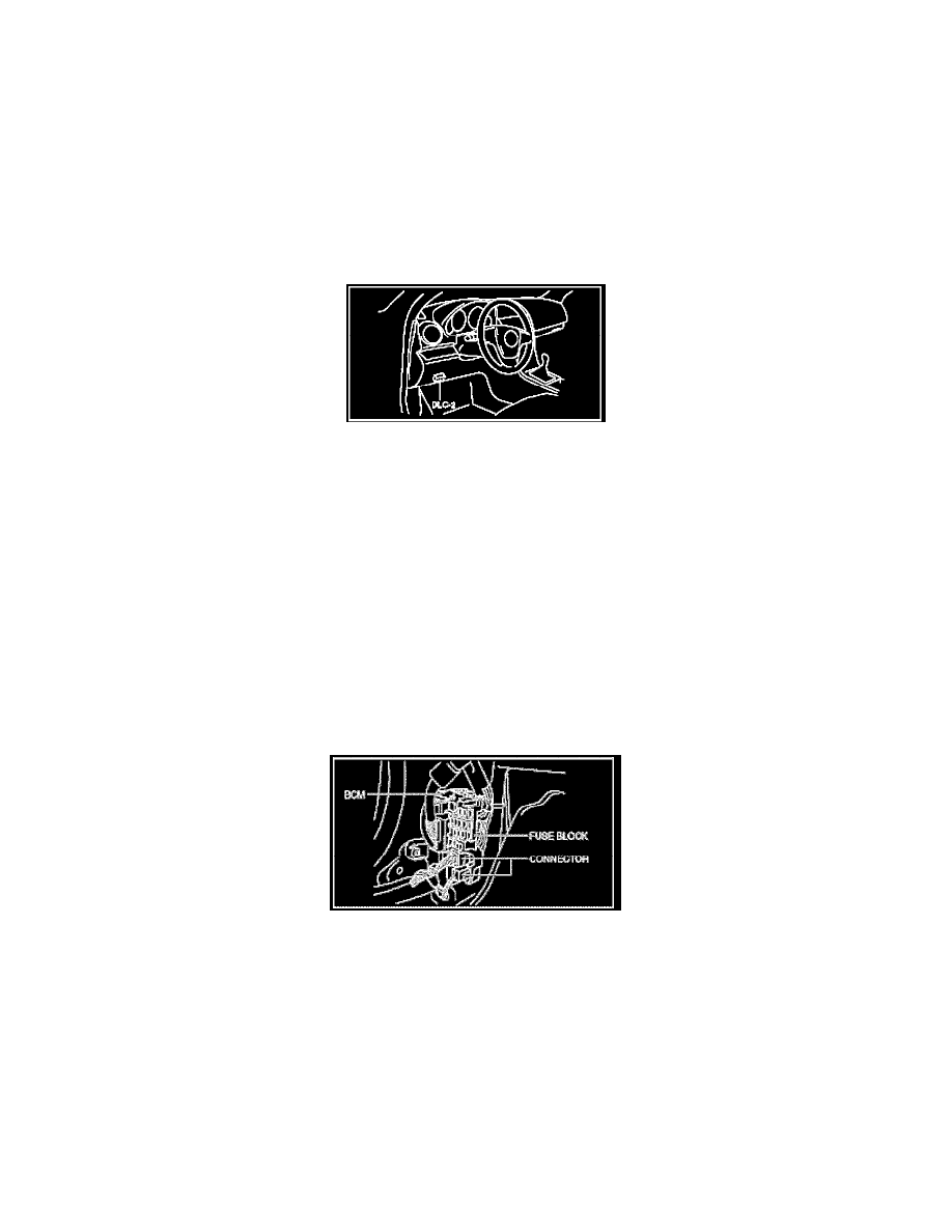
1. Connect the M-MDS to the DLC 2.
2. After the vehicle is identified, select the following items from the initialization screen of the M-MDS.
-
When using the IDS (laptop PC)
1. Select "DataLogger".
2. Select "Modules".
3. Select "BCM/GEM".
-
When using the PDS (Pocket PC)
1. Select "Module Tests".
2. Select "BCM/GEM".
3. Select "DataLogger".
3. Select the PART#_PFX
4. Verify the PID data according to the directions on the screen.
Procedure for verifying BCM part number without using M-MDS
1. Remove the front scuff plate (driver-side).
2. Remove the front side trim (driver-side).
3. Disconnect the connector at the position shown in the figure.
4. Remove tab A as shown in the figure,pull the fuse block in the direction of the arrow (1), and remove tab B.