
6 L4-2.5L (2010)
a. Switch the ignition to off.
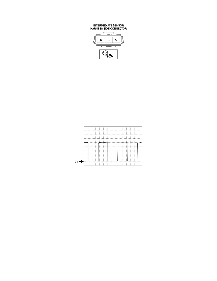
b. Measure the voltage at intermediate sensor connector terminal C (harness-side).
-
If there is any malfunction, repair wiring harness between intermediate sensor and TCM.
Intermediate sensor specification
-
Below 1.0 V
3. Inspect the signal circuit for the intermediate sensor.
a. Connect the oscilloscope to the following TCM connector terminals and set it as below.
-
(+) lead: TCM terminal 2L
-
(-) lead: battery negative terminal
-
Oscilloscope setting: 1 V/DIV (Y), 2 ms/DIV (X), DC range
b. Start the engine.
c. Measure the wave form when vehicle speed at 30 km/h {19 mph}.
-
If there is any malfunction, replace the intermediate sensor. See: Service and Repair/Intermediate Sensor Removal/Installation - FS5A-EL
Vehicle Speed Sensor (VSS) Inspection - AW6A-EL
VEHICLE SPEED SENSOR (VSS) INSPECTION [AW6A-EL]
CAUTION:
-
Water or foreign objects entering the connector can cause a poor connection or corrosion. Be sure not to drop water or foreign objects on the
connector when disconnecting it.
-
Do not damage the terminals.
Resistance Inspection
1. Disconnect the negative battery cable.
2. Remove the air cleaner component. See: Engine, Cooling and Exhaust/Engine/Intake Manifold/Service and Repair
3. Remove the TCM. See: Powertrain Management/Transmission Control Systems/Relays and Modules - Transmission and Drivetrain/Relays and
Modules - A/T/Control Module/Service and Repair/TCM Removal/Installation - AW6A-EL
4. Verify that there is no continuity between the coupler component terminals B19 and GND or B20 and GND.