
6 V6-3.7L (2009)
Hydraulic Control Assembly - Antilock Brakes: Service and Repair
DSC HU/CM Removal/Installation
DSC HU/CM REMOVAL/INSTALLATION
CAUTION:
-
When replacing the DSC HU/CM, the configuration procedure must be done before removing the DSC HU/CM. If the configuration is not
completed before removing the DSC HU/CM, DSC will not work properly after installation of the DSC HU/CM.
-
The internal parts of the DSC HU/CM could be damaged if dropped. Be careful not to drop the DSC HU/CM. Replace the DSC HU/CM if it is
subjected to an impact.
1. Remove the following parts:
a. Windshield wiper arm and blade See: Wiper and Washer Systems/Wiper Arm/Service and Repair
b. Cowl grille See: Body and Frame/Cowl/Cowl Moulding / Trim/Service and Repair/Cowl Grille Removal/Installation
c. Windshield wiper motor See: Wiper and Washer Systems/Wiper Motor/Service and Repair/Removal and Replacement
d. Cowl panel See: Body and Frame/Cowl/Cowl Moulding / Trim/Service and Repair/Cowl Panel Removal/Installation
2. Disconnect the brake pipes (master cylinder side). See: Brake Master Cylinder/Service and Repair
3. For the vehicles with MZI-3.7, perform the following steps.
a. Remove the power steering reserve tank component. See: Steering and Suspension/Steering/Power Steering/Power Steering Pump/Service and
Repair/Removal and Replacement
b. Disconnect the OCV connector. See: Engine, Cooling and Exhaust/Engine/Engine Lubrication/Engine Oil Control Valve/Service and Repair
c. Disconnect the ignition coil connector. See: Powertrain Management/Ignition System/Ignition Coil/Service and Repair
d. Disconnect the HO2S (RH) connector. See: Powertrain Management/Computers and Control Systems/Oxygen Sensor/Service and
Repair/Heated Oxygen Sensor (HO2S) Removal/Installation
e. Disconnect the pressure switch connector. See: Steering and Suspension/Steering/Power Steering/Power Steering Pump/Service and
Repair/Removal and Replacement
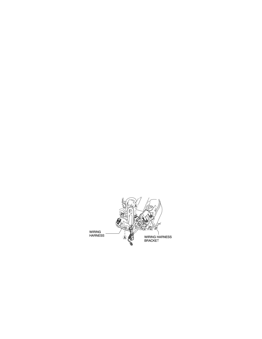
f.
Disconnect the wiring harness from the wiring harness bracket as shown in the figure.
g. Set the wiring harness out of the way.
4. Remove in the order indicated in the table.
5. Install in the reverse order of removal.
6. Add brake fluid, bleed the brakes, and inspect for leakage after the installation has been completed. See: Brake Bleeding/Service and Repair
7. Configurate the DSC HU/CM (only when replacing it). See: Testing and Inspection/Programming and Relearning/DSC Configuration
8. Clear the DTCs from the memory. See: Antilock Brakes / Traction Control Systems/Testing and Inspection/Scan Tool Testing and
Procedures/On-Board Diagnosis [Dynamic Stability Control (Dsc)]