
6 V6-3.7L (2009)
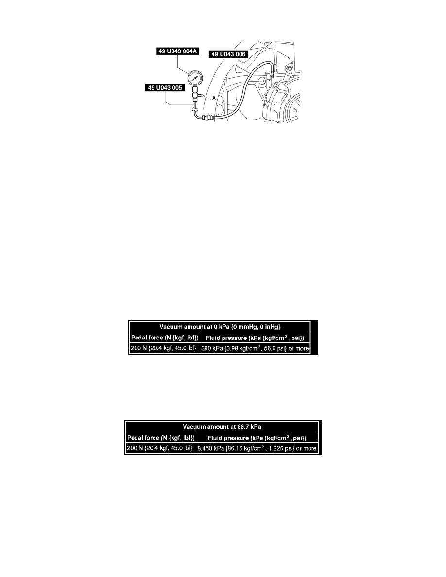
4. Install the SSTs to the brake pipe as shown in the figure.
5. Perform air bleeding of the SST and brake line from bleeder screw A.
6. Install the pedal force gauge to the brake pedal.
7. Connect the vacuum piping to the vacuum gauge.
Checking for vacuum loss (loaded condition)
1. Start the engine.
2. Depress the brake pedal with a force of 200 N {20.4 kgf, 45.0 lbf}.
3. Stop the engine when the vacuum gauge reading reaches 68 kPa {510 mmHg, 20 inHg} with the pedal depressed.
4. Measure the amount of vacuum decrease for 15 s immediately after stopping the engine.
5. If the gauge indicates a drop of 3.3 kPa {25 mmHg, 0.97 inHg} or less, the unit is normal.
Non-servo operation inspection
1. If the pedal force and fluid pressure correlation is within the specification with the engine stopped and a vacuum amount of 0 kPa {0 mmHg, 0
inHg}, the system is normal. Standard power brake unit non-servo operation
Servo operation inspection
1. Start the engine and depress the brake pedal when the vacuum reaches 66.7 kPa {500 mmHg, 19.7 inHg}.
2. At this time, apply the indicated pedal force and if the fluid pressure is within the specification, the unit is normal.
Standard power brake unit servo operation
Procedure after inspection
1. Remove the SSTs after the inspection and install the bracket, brake hose and brake pipe to their original positions. See: Hydraulic System/Brake
Hose/Line/Service and Repair/Brake Hose (Front) Removal/Installation
2. Perform air bleeding of the brake line. See: Brake Bleeding/Service and Repair