
6 V6-3.7L (2009)
Valve Clearance: Testing and Inspection
VALVE CLEARANCE INSPECTION/ADJUSTMENT [MZI-3.7]
Valve Clearance Inspection
1. Disconnect the negative battery cable.
2. Remove the engine cover. See: Service and Repair/Removal and Replacement/Engine Cover Removal/Installation
3. Remove the ventilation hose.
4. Remove the dynamic chamber and throttle body as a single unit. See: Intake Manifold/Service and Repair
5. Disconnect the wiring harness.
6. Remove the ignition coils. See: Powertrain Management/Ignition System/Ignition Coil/Service and Repair
7. Remove the dipstick.
8. Remove the cylinder head cover. See: Timing Components/Timing Chain/Service and Repair
9. Remove the splash shield (RH).
10. Measure the valve clearance.
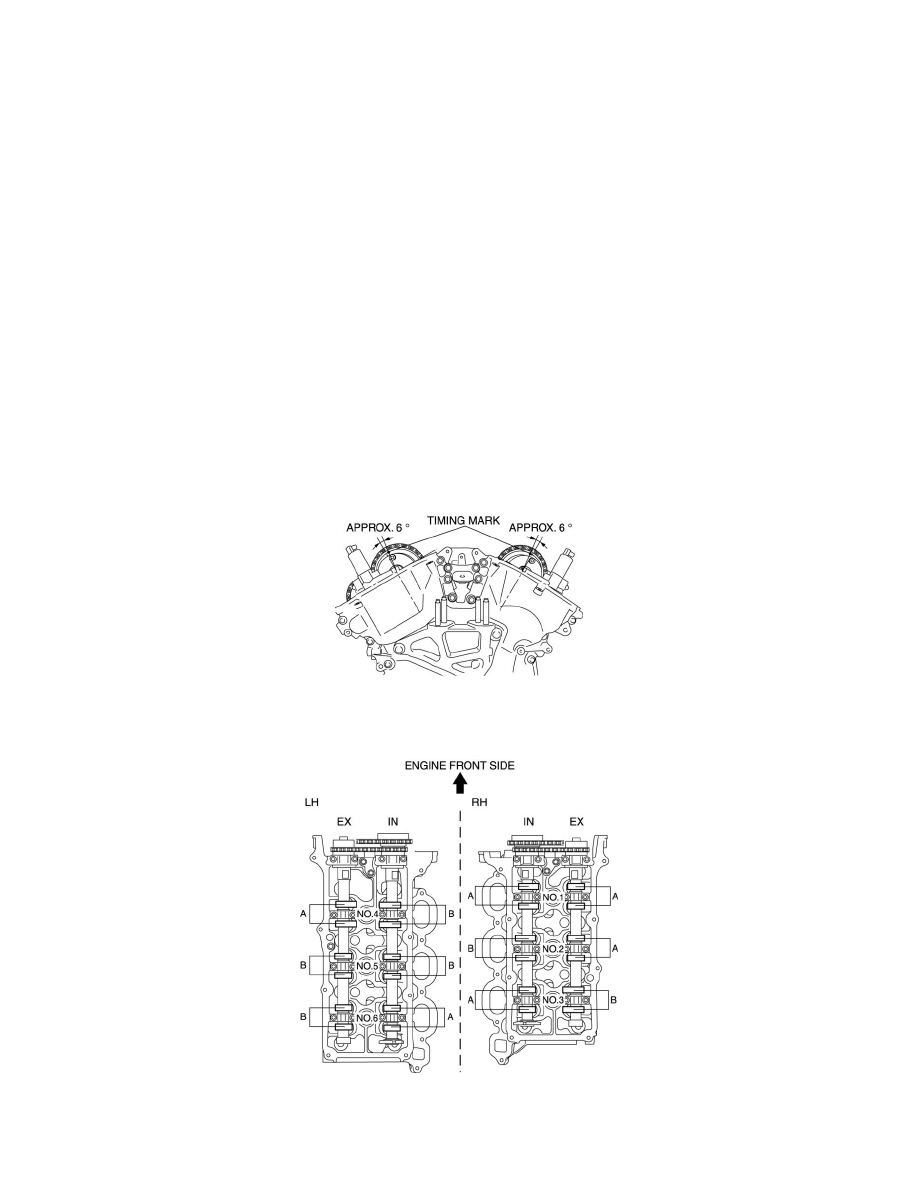
a. Rotate the crankshaft clockwise and verify that the timing mark of the intake side camshaft sprocket is in the position shown in the figure. In
this position, the No.1 cylinder is at the TDC of the compression stroke.
b. Measure the valve clearance of location A shown in the figure.
-
If it is not within the specification, replace the tappet and adjust the valve clearance to the median value of the standard.
Standard valve clearance [Engine cold]
-
IN: 0.150-0.250 mm {0.00591-0.00984 in}
-
EX: 0.300-0.400 mm {0.0119-0.0157 in}