
6 V6-3.7L (2009)
Tool size
-
TORX: T55
-
TORX PLUS: 55IP
4. Tighten the new camshaft sprocket (RH) bolts using the appropriate tools following 4 steps.
a. Tighten to 40 Nm {4.1 kgf-m, 30 ft-lbf}.
b. Loosen 360 ° (one full turn) in reverse order.
c. Tighten to 10 Nm {102 kgf-cm, 89 in-lbf}.
d. Tighten to 90 °.
5. Install the variable valve timing actuator, camshaft timing chain and the exhaust camshaft sprocket of the LH bank as a single unit.
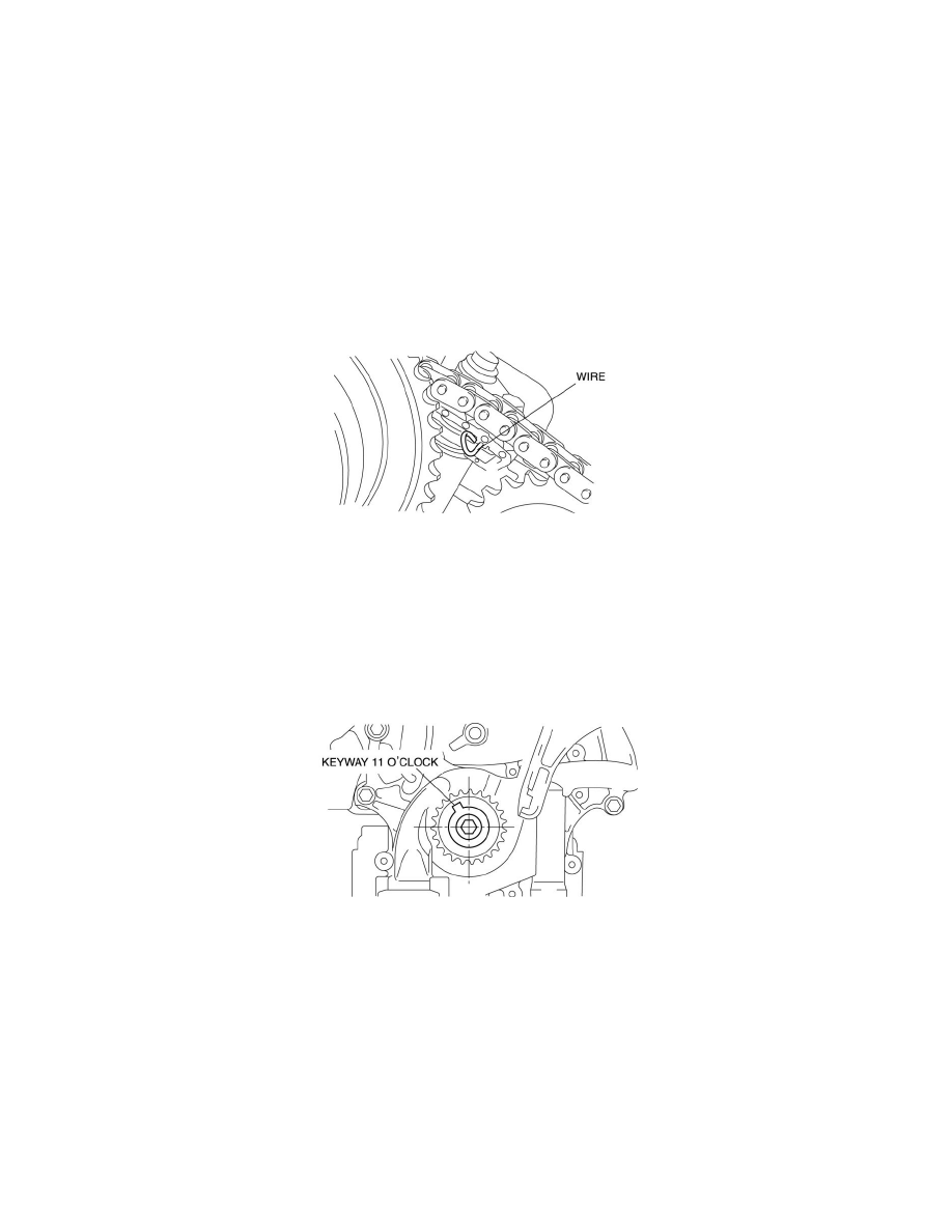
6. Remove the retaining wire inserted into the camshaft timing chain tensioner (LH).
7. Tighten the new camshaft sprocket (LH) bolts using the appropriate tools following 4 steps.
a. Tighten to 40 Nm {4.1 kgf-m, 30 ft-lbf}.
b. Loosen 360 ° (one full turn) in reverse order.
c. Tighten to 10 Nm {102 kgf-cm, 89 in-lbf}.
d. Tighten to 90 °.
8. Turn the crankshaft clockwise so that the crankshaft keyway is in the 11 o'clock position. (This will position the No.1 cylinder at TDC.)
9. Follow the "TIMING CHAIN REMOVAL/INSTALLATION" procedure and install the timing chain. See: Engine, Cooling and
Exhaust/Engine/Timing Components/Timing Chain/Service and Repair