
6 V6-3.7L (2009)
VSS specification
-
4.5-5.5 V
e. Switch the ignition to off.
f.
Connect the VSS connector.
2. Inspect the GND circuit for the VSS.
a. Switch the ignition to off.
b. Measure the voltage at intermediate sensor connector terminal C (harness-side).
-
If there is any malfunction, repair wiring harness between intermediate sensor and TCM.
Intermediate sensor specification
-
Below 1.0 V
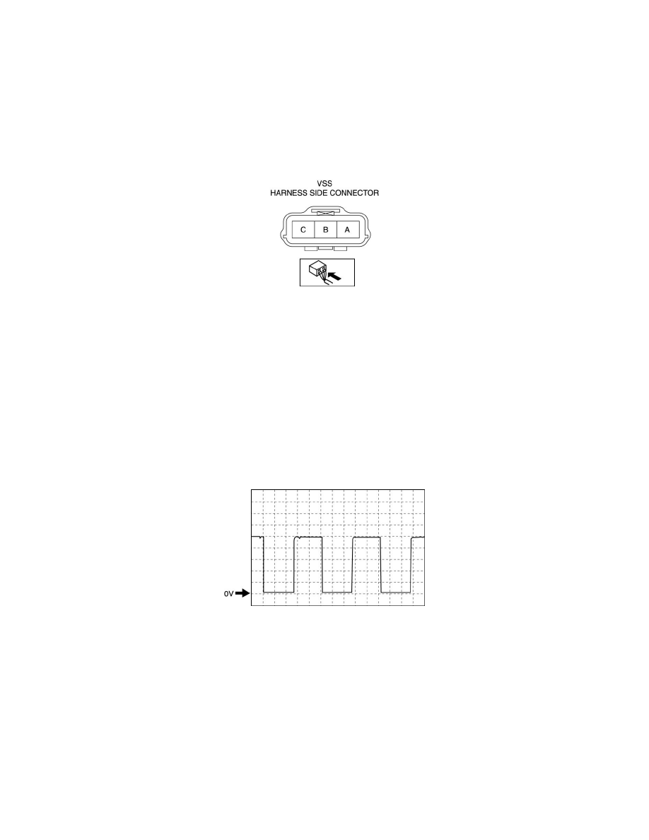
3. Inspect the signal circuit for the VSS.
a. Connect the oscilloscope to the following TCM connector terminals and set it as below.
-
(+) lead: TCM terminal 2P
-
(-) lead: battery negative terminal
-
Oscilloscope setting: 1 V/DIV (Y), 2 ms/DIV (X), DC range
b. Start the engine.
c. Measure the wave form when vehicle speed at 30 km/h {19 mph}.
-
If there is any malfunction, replace the VSS. See: Service and Repair/Vehicle Speed Sensor (VSS) Removal/Installation [FS5A-EL]
Input/Turbine Speed Sensor Inspection [AW6A-EL]
INPUT/TURBINE SPEED SENSOR INSPECTION [AW6A-EL]
CAUTION:
-
Water or foreign objects entering the connector can cause a poor connection or corrosion. Be sure not to drop water or foreign objects on the
connector when disconnecting it.
-
Do not damage the terminals.
On-Vehicle Inspection
1. Disconnect the negative battery cable.