
6 V6-3.7L (2009)
Intermediate sensor specification
-
Below 1.0 V
3. Inspect the signal circuit for the intermediate sensor.
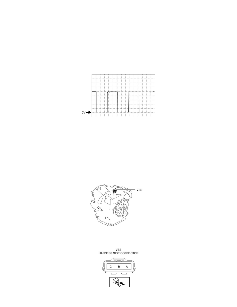
a. Connect the oscilloscope to the following TCM connector terminals and set it as below.
-
(+) lead: TCM terminal 2L
-
(-) lead: battery negative terminal
-
Oscilloscope setting: 1 V/DIV (Y), 2 ms/DIV (X), DC range
b. Start the engine.
c. Measure the wave form when vehicle speed at 30 km/h {19 mph}.
-
If there is any malfunction, replace the intermediate sensor. See: Service and Repair/Intermediate Sensor Removal/Installation [FS5A-EL]
Vehicle Speed Sensor (VSS) Inspection [FS5A-EL]
VEHICLE SPEED SENSOR (VSS) INSPECTION [FS5A-EL]
On-Vehicle Inspection
1. Inspect the power supply circuit for the VSS.
a. Remove the aerodynamic under cover NO.2. See: Body and Frame/Splash Guard/Service and Repair/Aerodynamic Under Cover No.2
Removal/Installation
b. Disconnect the VSS connector.
c. Switch the ignition to ON (engine off).
d. Measure the voltage at VSS connector terminal A (harness-side).
-
If there is any malfunction, repair wiring harness between VSS and TCM.