
626 L4-1998 cc 2.0L SOHC Turbo FE (1986)
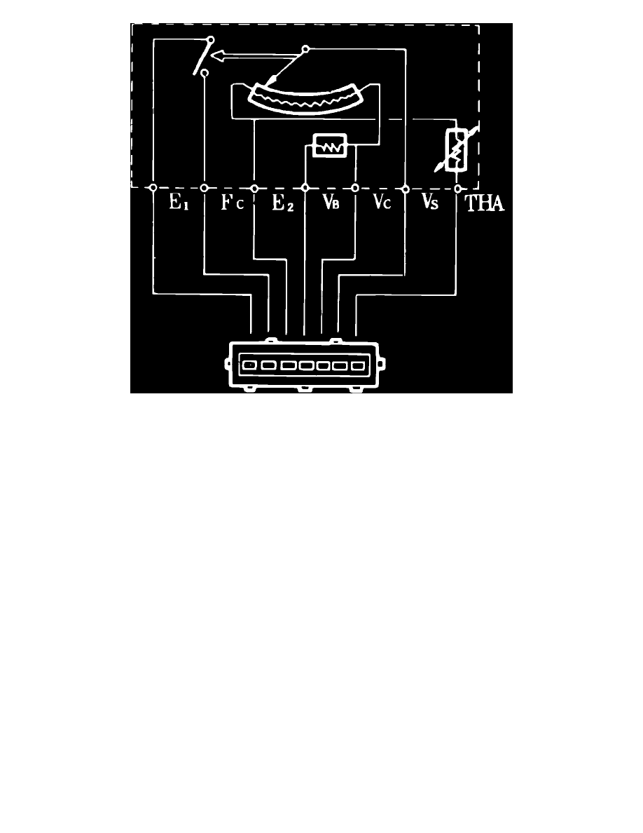
Fig. 25 Air flow meter terminal identification.
6.
Using ohmmeter, measure resistance between terminals as follows:
a. Resistance between terminals E2 and VS, Fig. 25, should be greater than 20 ohms.
b. Resistance between terminals E2 and VC should be 100-300 ohms.
c. Resistance between terminals E2 and VB should be 200-400 ohms.
d. Resistance between E2 and THA should be 13.6-18.4k ohms at 4°F, 2.205-2.695k ohms at 68°F and .493-.667k ohms at 140°F.
e. Resistance between terminals E1 and FC should be infinite.
7.
Press open measuring plate.
8.
Using an ohmmeter, check resistance between terminals of connector. Resistance between terminals E2 and VS should be less than 400 ohms.
There should be no resistance between terminals E1 and FC.
9.
If resistance is not within specifications, replace air flow meter assembly.